190-00207-02 GTX 330/330D Installation Manual
Rev. U Page 2-5
2.6 Installation Approval Considerations for Pressurized Aircraft
Antenna and cable installations on pressurized cabin aircraft require FAA approved installation design and
engineering substantiation data whenever such installations incorporate alteration (penetration) of the
cabin pressure vessel by connector holes and/or mounting arrangements.
For needed engineering support pertaining to the design and approval of such pressurized aircraft antenna
installations, it is recommended that the installer proceed according to any of the following listed
alternatives:
1. Obtain approved antenna installation design data from the aircraft manufacturer.
2. Obtain an FAA approved Supplemental Type Certificate (STC) pertaining to and valid for the
subject antenna installation.
3. Contact the FAA Aircraft Certification Office in the appropriate Region and request identification
of FAA Designated Engineering Representatives (DERs) who are authorized to prepare and
approve the required antenna installation engineering data.
4. Obtain FAA Advisory Circular AC-183C and select (and contact) a DER from the roster of
individuals identified thereunder.
5. Contact an aviation industry organization such as the Aircraft Electronics Association and request
their assistance.
2.7 Cooling Air
The GTX 330 meets all applicable TSO requirements without forced air cooling. The application of forced
air cooling to the rear air nozzle of the GTX 330 is highly recommended to provide beneficial cooling to
the unit.
The GTX 330 was designed to handle a constant interrogation of 450 Pulse Repetition Frequency (PRF)
per second, with short periods of 1200 PRF. Rate limit is set at 1200 PRF. A typical radar site would
interrogate the transponder once every 5 to 10 seconds for approximately 100 milliseconds at a 400 PRF
rate. In very high traffic areas with multiple ground stations and TCAS traffic it is possible to have long
term PRF rates above 450 PRF.
2.8 GTX 330 Installation
2.8.1 Viewing Angle
Ensure that any mounting location will offer sufficient viewing angle. The display has been proven to
meet specifications when seen within the envelope of viewing positions listed in Table 2-4.
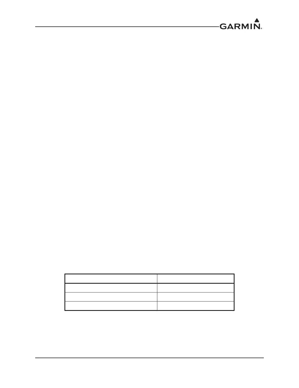
Table 2-4 Viewing Angles
Direction Pilot’s Viewing Angle
Left and Right ±45°
From Top 30°
From Bottom 10°
 Loading...