GE Grid Solutions
994-0081-3.00-21 GE Information
Chapter 7: Upgrading and Replacing D25
Modules
Remedial
Maintenance
If a board has failed on your D25 or you need to upgrade a specific
component, use this section of the guide, which explains:
• How to remove and replace the main boards
• How to enable and disable Serial XCOM Radio Keying
• How to access and change Ethernet XCOM jumpers
• How to change the power supply jumpers
• How to change Input and Output cards and CT/PT interface modules
• How to reconnect power
Module Replacement
About the D25
Modules
• All modules are accessed through the front of the enclosure.
• I/O modules can be removed and replaced without disturbing field wiring.
• Each printed circuit board (PCB) fits into a guide in the enclosure side panels.
• Each daughter board has self-aligning connectors to ensure correct insertion.
• All PCBs of different types are keyed to prevent improper insertion into the
wrong location.
Component
Location
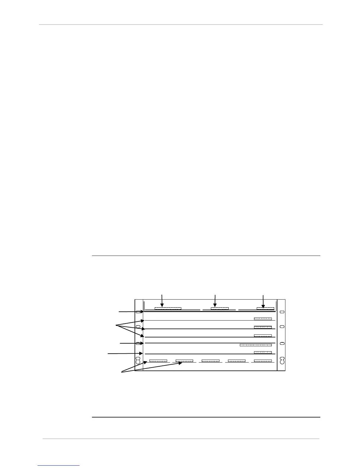
With the front panel removed and the D25 WESDAC module removed, the
modules are located as shown:
D25 PCB/Connector Layout
(Front View – WESDAC Card Removed)
Card
Card

 Loading...


