GE Grid Solutions
GE Information 994-0081-3.00-21
Installation Steps, Continued
7 If the FLASH memory has been deleted or corrupted, then you
need to download the code and configuration files. See Chapter 4:
Configuring the D25 Software.
8 If you have to download code and configuration files, then go back
to step 5 and verify that the D25 is now operating correctly.
Note
If you are replacing a component that is already installed on the D25 or
upgrading a specific component, then see Chapter 7: Upgrading and
Replacing D25 Modules.
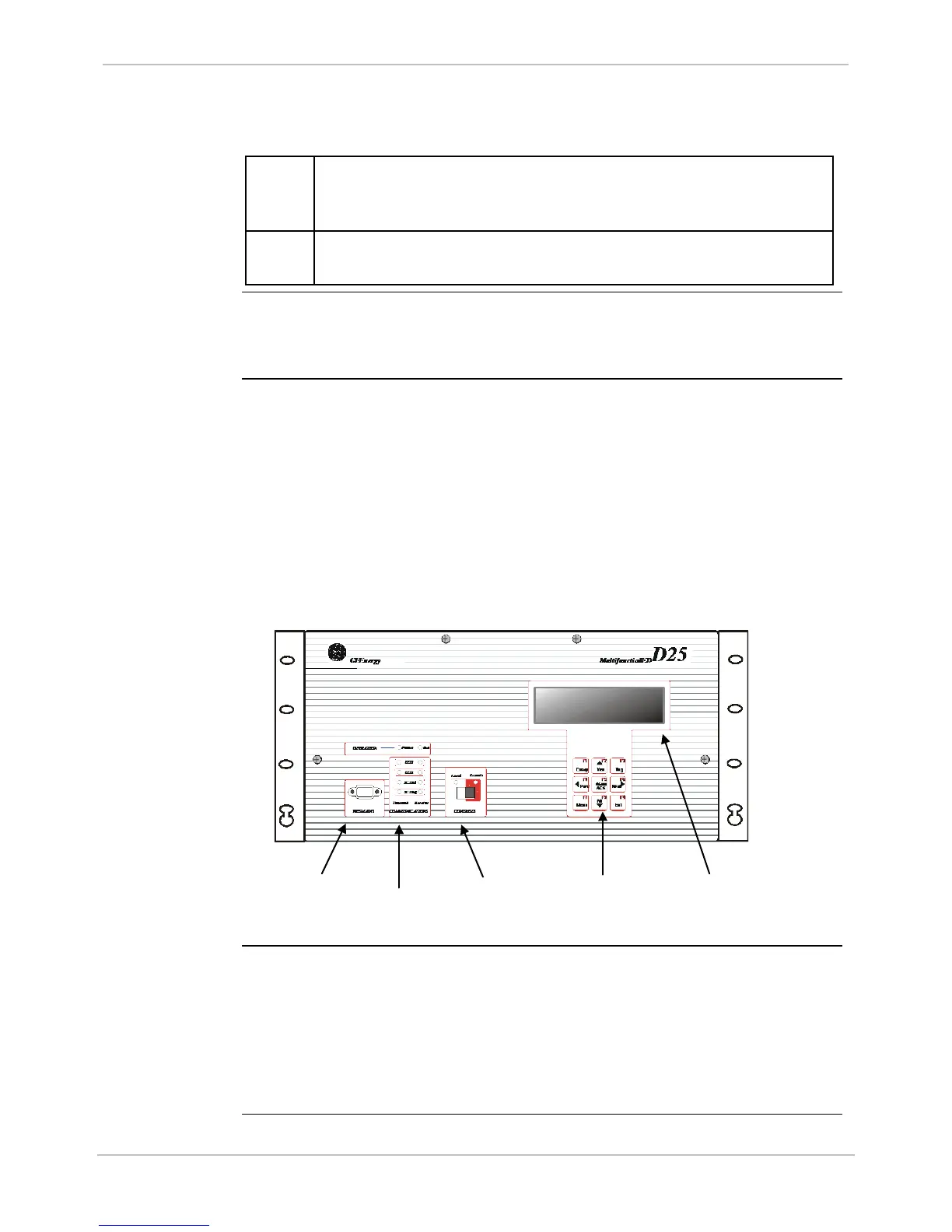
First Look at the D25
Front Panel
• WESMAINT II+ connector for connecting a maintenance terminal or PC
• LEDs for information on status, operation and traffic on communication ports
• CONTROLS switch for setting Local or Remote operational state of the digital
output module
• Optional LCD Display to display selected data stored in the D25 database
• Keypad for using the menus shown on the LCD Display. Only present if LCD
option is included
Back Panel
The D25 back panel is modular with removable sections. The types and
number of connectors are specified when the unit is ordered but can be
changed in the field.
There are two back panel options for the D25KE control board:
• Termination with six DB-25 connectors
• Termination with two FACE40 connectors
CONNECTOR
INDICATOR
DISPLAY
LCD or Touch
Screen Graphical

 Loading...


