GE Grid Solutions
994-0081-3.00-21 GE Information
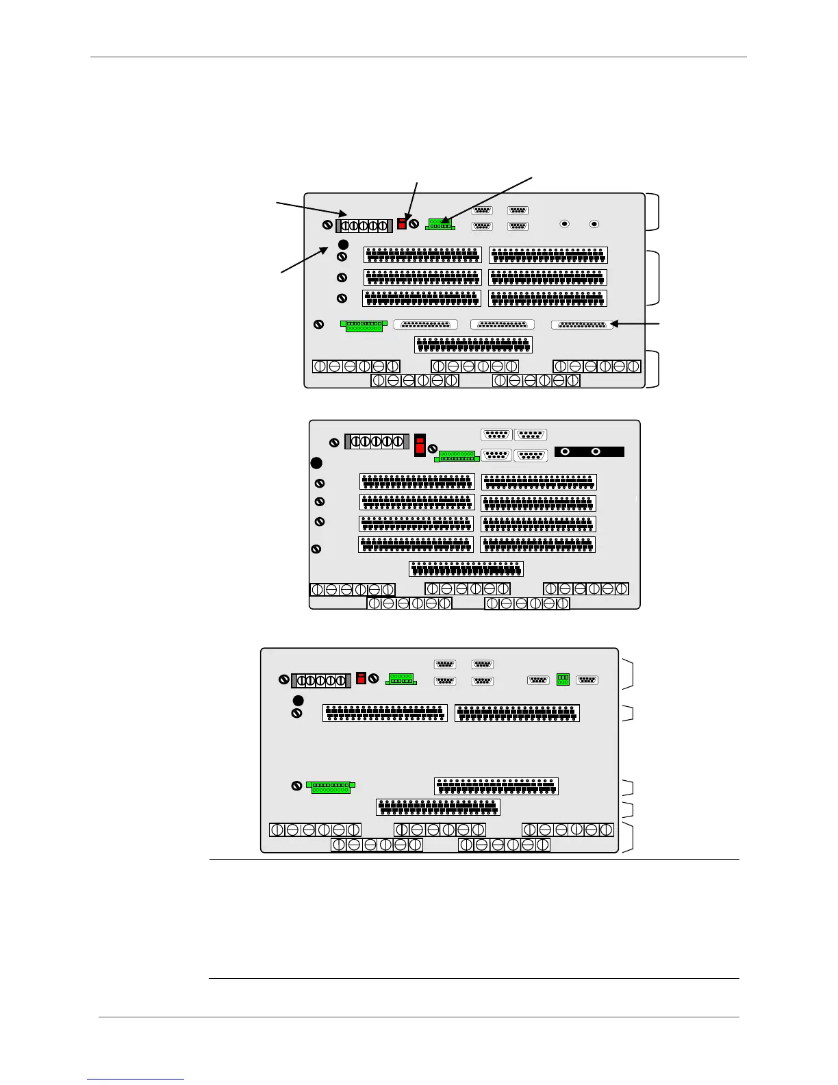
First Look at the D25, Continued
Back Panel
Diagrams
With six DB-25 connectors:
ON
OFF
POWER
A
D25 MAINT
IED 1
IED 2
UTC
C
E
B
D
F
DC
INPUTS
GND
XCOM 1
XCOM 2
J1 J2 J3
P1 P3 P5 P7 P9
P2 P4 P6 P8
1 3 5 7 9 11 13 15 17 19 21 23 25 27 29 31 33 35 37 39
2 4 6 8 10 12 14 16 18 20 22 24 26 28 30 32 34 36 38 40
2 1 2 1 2 1
FAIL AUX KEY
SYS RADIO
1 3 5 7 9 11 13 15 17 19 21 23 25 27 29 31 33 35 37 39
2 4 6 8 10 12 14 16 18 20 22 24 26 28 30 32 34 36 38 40
1 3 5 7 9 11 13 15 17 19 21 23 25 27 29 31 33 35 37 39
2 4 6 8 10 12 14 16 18 20 22 24 26 28 30 32 34 36 38 40
STATUS 1
FUSE - F3
STATUS 2 –
FUSE - F4
STATUS 3: -
FUSE - F5
FIELD
OUTPUT
FUSE – F1
PS FUSE
F2
With two FACE-40 connectors:
Legacy System Back Panel:
AUXILIARY CONTROLS
B
D
F
H
DC ANALOG
INPUTS
P1 P3 P5 P7 P9
P2 P4 P6 P8
2 4 6 8 10 12 14 16 18 20 22 24 26 28 30 32 34 36 38 40
1 3 5 7 9 11 13 15 17 19 21 23 25 27 29 31 33 35 37 39
2 4 6 8 10 12 14 16 18 20 22 24 26 28 30 32 34 36 38 40
1 3 5 7 9 11 13 15 17 19 21 23 25 27 29 31 33 35 37 39
2 4 6 8 10 12 14 16 18 20 22 24 26 28 30 32 34 36 38 40
G
CONTROL
OUTPUTS
2 4 6 8 10 12 14 16 18 20 22 24 26 28 30 32 34 36 38 40
AC ANALOG
INPUTS
DC ANALOG
INPUTS
CONTROL
OUTPUTS
DIGITAL
INPUTS
COMMUNICATION
PORTS
XCOM 1 XCOM 2TB 31
CTRL PWR
FUSE – F6
ON
OFF
POWER
D25 MAINT
IED 1
IED 2
UTC
2 1 2 1 2 1
FAIL AUX KEY
SYS RADIO
FIELD
OUTPUT
FUSE – F1
PS FUSE
F2
A
GND
STATUS 1
FUSE - F3
Part Number
The part number label on the rear of the enclosure identifies the D25 options
at the time of delivery (See Appendix C: Ordering Information):
• Each digit in the part number indicates the options included in the D25
• If the D25 is modified after delivery, the part number may no longer represent
the options accurately
• Update the part number label to match any option changes made after delivery
POWER
A
D25 MAINT
IED / HOST 1
IED / HOST 2
UTC
C
B
D
DC ANALOG
INPUTS
GND
XCOM 1
XCOM 2
SYS
FAIL AUX KEY
6 5 4 3 2 1
RADIO
1 3 5 7 9 11 13 15 17 19 21 23 25 27 29 31 33 35 37 39
2 4 6 8 10 12 14 16 18 20 22 24 26 28 30 32 34 36 38 40
1 3 5 7 9 11 13 15 17 19 21 23 25 27 29 31 33 35 37 39
2 4 6 8 10 12 14 16 18 20 22 24 26 28 30 32 34 36 38 40
1 3 5 7 9 11 13 15 17 19 21 23 25 27 29 31 33 35 37 39
2 4 6 8 10 12 14 16 18 20 22 24 26 28 30 32 34 36 38 40
H
E F
G2
G1
PORTS
INPUTS
OUTPUTS

 Loading...


