GE Grid Solutions
994-0081-3.00-21 GE Information
Digital Output Card
KE Card
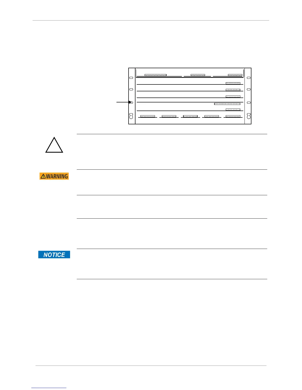
Mount the KE Card component-side down in the fifth slot (from the top of the
D25):
Use Pullers
Always use the pullers shipped with the D25 to remove and replace KE Card.
The high voltage area of the D25 High Current KE Digital Output Module is in close
proximity to the D25 chassis. Ensure that relay contacts are de-energized before
removing the D25 HCKE Digital Output Module.
Removing the
KE Card
Using one PCB puller, slide the KE Card toward the front of the D25.
Use firm but gentle pressure when pulling the card out.
Replacing the
KE Card
Position the KE Card component side down in the fifth slot from the top of
the D25, and carefully push the card into the D25 housing.
Use firm but gentle pressure to push the card into place.
KE Card
The KE Card must be installed component side down.
Attempts to install the KE Card in any other orientation will cause damage to
the components.
(Upside Down)

 Loading...


