GE Grid Solutions
GE Information 994-0081-3.00-21
DC Analog Inputs
DC Analog
Inputs
• All DC Analog Card options are available with 16 inputs.
• The inputs may be voltage or current.
• With the exception of the 517-0478 and 517-0479 cards that use adapter
modules, there are no on-board option jumpers; each option requires a different
card.
Shielding
All inputs should have shield connected at source of signal. Shields can
alternately be connected to the auxiliary ground on D25 power supply
terminal block. DO NOT ground at both ends of cable.
Table: Digital
Counts
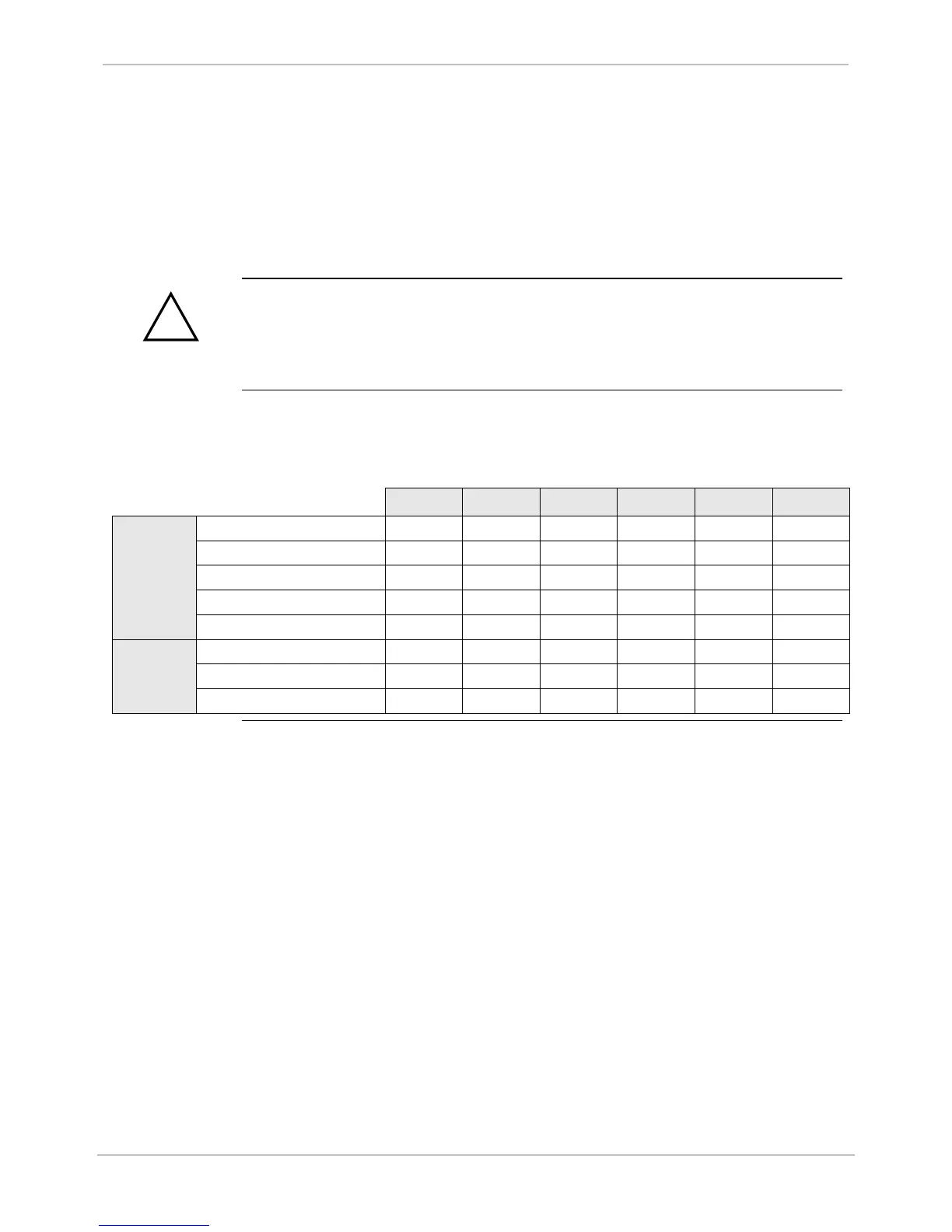
Table of typical digital counts stored in the D25 System Point Database
representing inputs at several input levels, and scaling settings, for each DC
Analog board option:
10% 25% 50% 75% Nom 120%
± 5V .5V 1.25V 2.5V 3.75V 5V 6V
± 1 mA .1 mA .25 mA .5 mA .75 mA 1 mA 1.2 mA
± 5 mA .5 mA 1.25 mA 2.5 mA 3.75 mA 5 mA 6 mA
± 10 mA 1 mA 2.5 mA 5 mA 7.5 mA 10 mA 12 mA
± 20 mA 2 mA 4 mA 10 mA 15 mA 20 mA 24 mA
@ 83.333% Scaling 2731 6826 13653 20479 27306 32767
@ 100% Scaling 3277 8192 16383 24575 32767 >32767
@ 200% Scaling 6553 16383 32767 >32767 >32767 >32767

 Loading...


