GE Grid Solutions
994-0081-3.00-21 GE Information
Connector G1 Connector G2
Pin Signal Description Pin Signal Description
G1-39 16A Channel # 16 NO A terminal G2-39 32C Channel # 32 Common terminal
G1-40 16B Channel # 16 NO B terminal G2-40 32NO Channel # 32 NO terminal
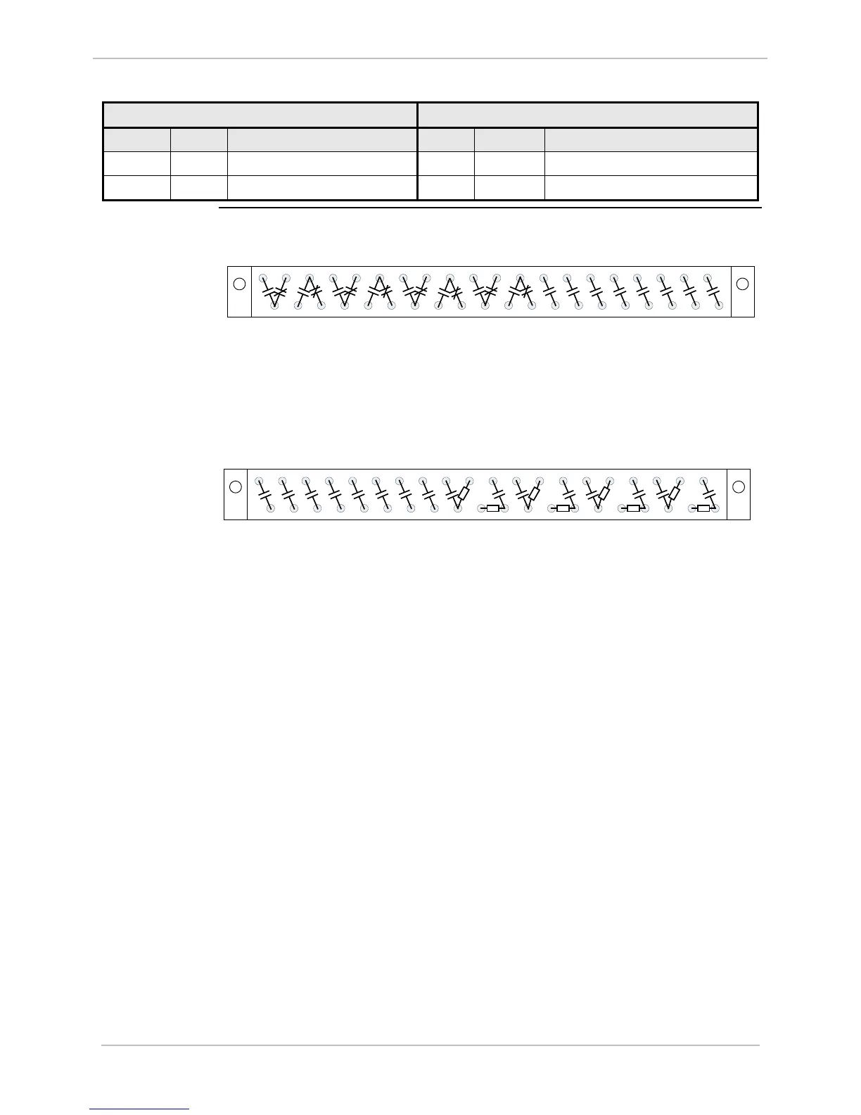
Figure:
Connectors G1
& G2 Pinouts
Layout
1
DO17
3
DO18
5
DO19
7
DO20
9
DO21
11
DO22
13
DO23
15
DO24
17
DO25
19
DO32
21
DO26
23
DO27
25
DO31
27
DO28
29
DO29
31
DO30
33 35 37 39
C
M
C
M
C
M
C
M
CMCM CM CM
2 4 6 8 10 12 14 16 18 20 22 24 26 28 30 32 34 36 38 40
Connector G2
1
DO1
3
DO2
5
DO15
7
DO12
9
DO3
11
DO4
13
DO11
15
DO5
17
DO6
19
DO16
21
DO7
23
DO8
25
DO14
27
DO9
29
DO10
31
DO13
33 35 37 39
2 4 6 8 10 12 14 16 18 20 22 24 26 28 30 32 34 36 38 40
Connector G1

 Loading...


