GE Grid Solutions
994-0081-3.00-21 GE Information
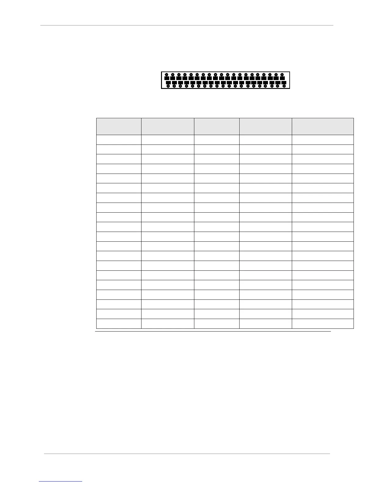
DC Analog Inputs, Continued
Table: DC
Analog Input
Connector
Pinout
1 3 5 7 9 11 13 15 17 19 21 23 25 27 29 31 33 35 37 39
2 4 6 8 10 12 14 16 18 20 22 24 26 28 30 32 34 36 38 40
Location of adapters on the module’s PCB for each input:
Connector H
Pin #
SIGNAL Connector H
Pin #
SIGNAL Input Adapter
Location
1 Ain 1+ 2 Ain 1- M1
3 Ain 2+ 4 Ain 2- M2
5 Ain 3+ 6 Ain 3- M3
7 Ain 4+ 8 Ain 4- M4
9 Ain 5+ 10 Ain 5- M5
11 Ain 6+ 12 Ain 6- M6
13 Ain 7+ 14 Ain 7- M7
15 Ain 8+ 16 Ain 8- M8
17 N/C 18 N/C
19 N/C 20 N/C
21 N/C 22 N/C
23 N/C 24 N/C
25 Ain 9+ 26 Ain 9- M9
27 Ain 10+ 28 Ain 10- M10
29 Ain 11+ 30 Ain 11- M11
31 Ain 12+ 32 Ain 12- M12
33 Ain 13+ 34 Ain 13- M13
35 Ain 14+ 36 Ain 14- M14
37 Ain 15+ 38 Ain 15- M15
39 Ain 16+ 40 Ain 16- M16

 Loading...


