GE Grid Solutions
GE Information 994-0081-3.00-21
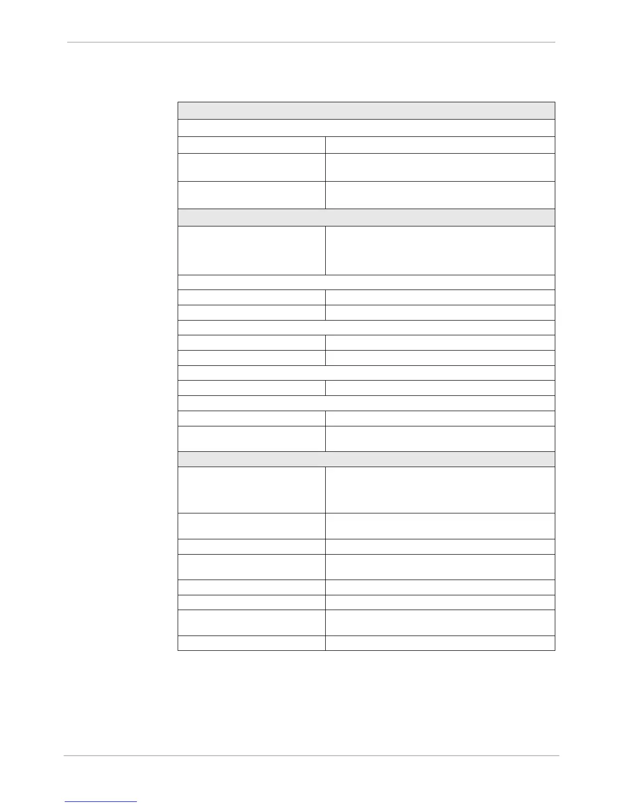
Electrical Specifications, Continued
Digital Inputs
Up to 96 optically isolated digital inputs, organized in groups of 32 units
“On” threshold options, per card 12, 24, 48, 120, 250 V
dc
±20%, bipolar inputs
Burden From 0.75 mA to 10 mA max. power dissipation is 0.5W
per input
Wetting Options Supplied - 24 or 48 V
dc
, isolated only, External wetting -
for all input options
Digital Outputs
D25KE 8, 16, 24, or 32 digital outputs with single component
failure protection and detection, preventing false control of
any coil driver output; select-check-before execute
security; master trip/close bus scheme.
Output Relay Contacts:
D25KE modules 1 From A
Maximum Switching Power 60 W (resistive) or 125 VA (resistive)
Maximum Switching Voltages:
D25KE DB-25 75 V
dc
or 50 V
ac
D25KE FACE-40 120 V
Maximum Switching Currents:
D25KE 2 A
Maximum Carrying Currents:
D25KE 2 A
Interposing Relay Option
Groups of eight digital outputs can be directly interfaced to
D20 KI modules
Digital Outputs – High Current Module
D25HC KE 32 isolated digital outputs with single component failure
protection and detection, preventing false control of any
coil driver output; select-check-before execute security; 8
outputs with optional current supervision seal-in function
Output Relay Contacts 8x 1 From C; 16x 1 Form A and 8x 1 Form A with optional
current seal-in function
Maximum Make Current 10A for 5 sec
Maximum Break Current 10A @ 28 V
dc;;
; 0.85A @ 60 V
dc
; 0.45A @ 120 V
dc
; 0.3A
@ 300 V
dc
Maximum Switching Voltages 300 V
dc
or 300 V
ac
Continuous Carry Current 4A
Current Sensing Level for Seal-in
Function
Min 60mA; max 200mA
Simultaneously Operated Outputs Maximum 16, include max 4 with current supervision

 Loading...


