GE Grid Solutions
994-0081-3.00-21 GE Information
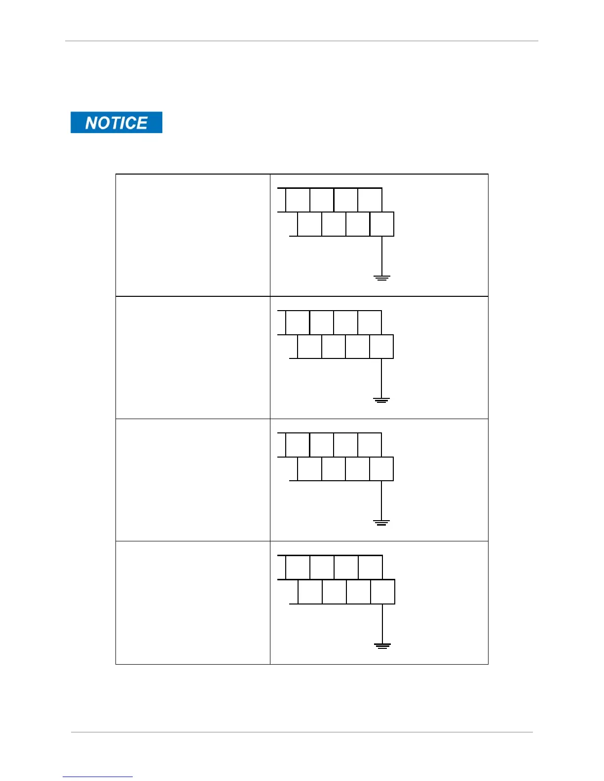
Connecting to Protective Ground
Connect your DNP3 I/O module to site ground, using a separate 2.05 mm (12 AWG) Yellow/ Green wire.
Each type of DNP I/O Module has a different ground point, as shown in the
examples below.
The location of the protective ground terminal varies between WESTERM I/O module types. Refer to
Module Layout drawing of your module for detailed information. For example, see below.
DC Analog Input Module
12 AWG
GND Wire
Site
Ground
100
47
97
48 49 50
98 99
TB1
Digital Input Module
12 AWG
GRN GND
Site
Ground
132
63
129
64 65 66
130 131
TB1
Control Output Module
12 AWG
GRN GND
Site
Ground
106
50
103
51
52 53
104 105
TB1
Combination Input Output
Module
Site
Ground
100
47
97
48 49 50
98 99
TB1
12 AWG
Green Wire
After site ground has been connected, you are now ready to connect power, and DNP3 link cabling to the
DNP3 I/O module. See section:
Connecting DNP3 I/O Modules (Low Voltage)
on page 165
or section:
Connecting DNP3 I/O modules (High Voltage) on page 166.

 Loading...


