GE Grid Solutions
994-0081-3.00-21 GE Information
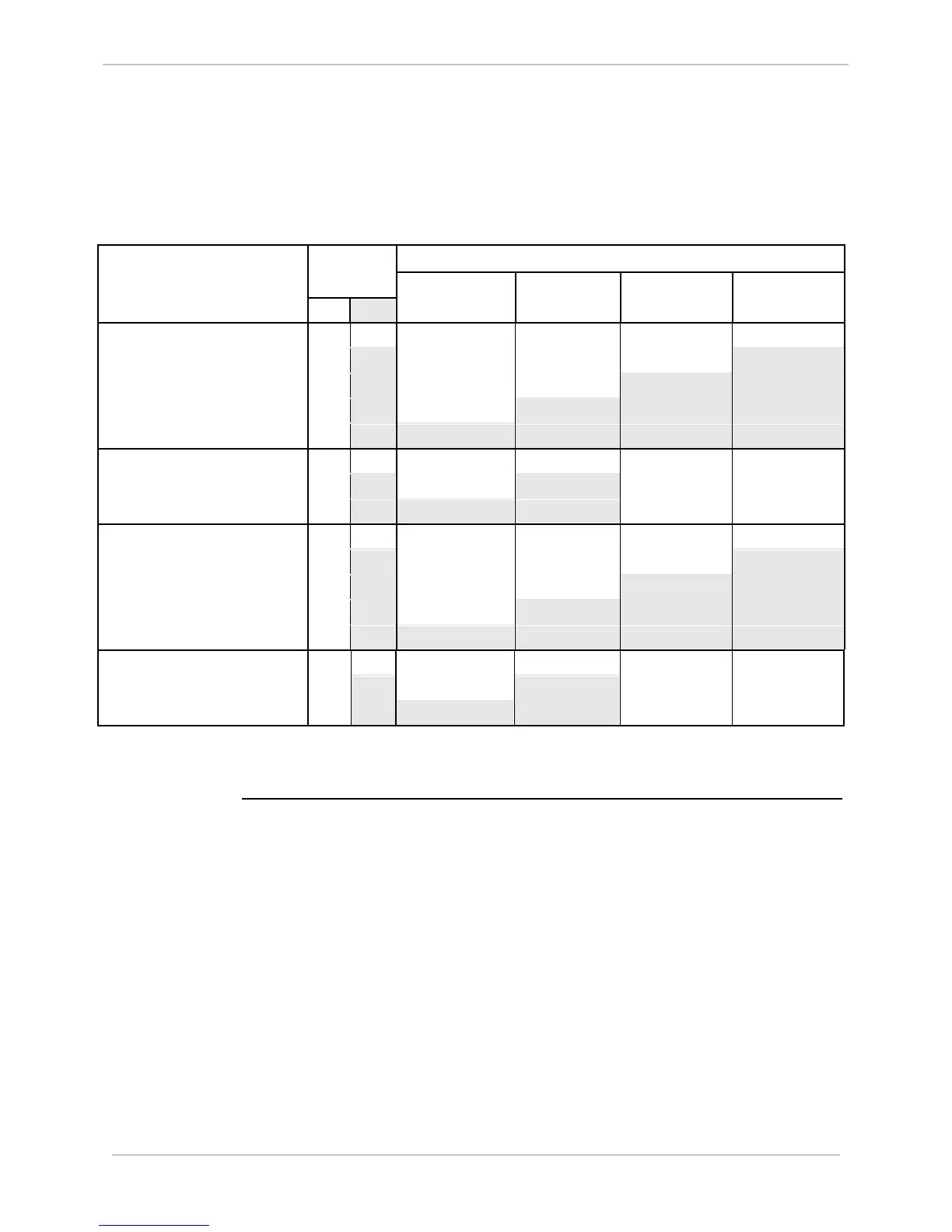
Control Outputs, Continued
Table:
Configuration
D25KE Configuration Summary
Product
Configuration
Jumper position
Relays 1-8 Relays 9-16 Relays 17-24 Relays 25-32
T/C R/L JMP1 JMP2 JMP3 JMP4
517-0443 D25KE Control Module
FACE40 32 Channel
32 0 G1/37-G1/39 G1/38-G1/40 G2/3-G2/5 G2/4-G2/6
24 4 G1/37-G1/39 G1/38-G1/40 G2/3-G2/5 G2/2-G2/4
16 8 G1/37-G1/39 G1/38-G1/40 G2/1-G2/3 G2/2-G2/4
8 12 G1/37-G1/39 G1/36-G1/38 G2/1-G2/3 G2/2-G2/4
0 16 G1/35-G1/37 G1/36-G1/38 G2/1-G2/3 G2/2-G2/4
517-0452 D25KE Control Module
FACE40 16 Channel
16 0 G1/37-G1/39 G1/38-G1/40 N/A N/A
8 4 G1/37-G1/39 G1/36-G1/38 N/A N/A
0 8 G1/35-G1/37 G1/36-G1/38 N/A N/A
517-0447 D25KE Control Module
DB25 32 Channel
32 0 P1/3-P1/6 P1/4-P1/6 P1/6-P1/7 P1/6-P1/8
24 4 P1/3-P1/6 P1/4-P1/6 P1/6-P1/7 P1/5-P1/8
16 8 P1/3-P1/6 P1/4-P1/6 P1/5-P1/7 P1/5-P1/8
8 12 P1/3-P1/6 P1/4-P1/5 P1/5-P1/7 P1/5-P1/8
0 16 P1/3-P1/5 P1/4-P1/5 P1/5-P1/7 P1/5-P1/8
517-0449 D25KE Control Module
DB25 16 Channel
16 0 P2/3-P1/6 P2/4-P2/6 N/A N/A
8 4 P2/3-P1/6 P2/4-P2/5 N/A N/A
0 8 P2/3-P1/5 P2/4-P2/5 N/A N/A
Note: Use GE part number 970-0264 Quad-Wire Jumper or plain wire of appropriate gauge to configure D25KE card.

 Loading...


