GE Grid Solutions
994-0081-3.00-21 GE Information
Types of Inputs
Implemented
on High
Current KE
Card (HCKE)
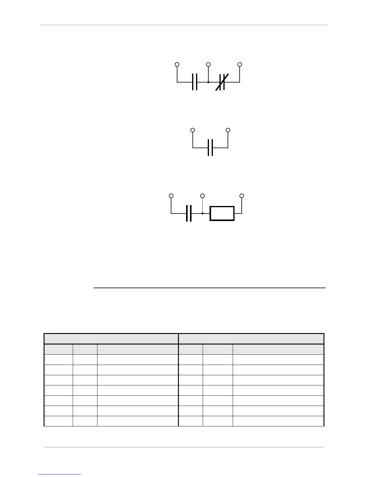
• 1 Form C (Control Outputs #1 through #8)
• 1 Form A (Control Outputs #9 through #24)
• 1 Form A with Current Monitoring (Control Outputs #25 through #32)
C
NO NO >I
1 Form A with Current
Monitoring Circuit
Current
Monitor
• When current supervision is required, the load shall be connected between
terminals C and NO >I. Otherwise the load should be connected between
terminals C and NO of the appropriate channel
• When current supervision is required, the load must be wired to terminal C and
NO >I of channels 25 to 32.
Table:
Connector G1
& G2 Pinouts
on HCKE
D25 High Current KE Digital Output Connections: Pinouts for FACE-40
Connector G1 and G2, outputs 1 to 32.
Connector G1 Connector G2
Pin Signal Description Pin Signal Description
G1-1 1NO Channel # 1 NO terminal G2-1 17A Channel # 17 NO A terminal
G1-2 1C Channel # 1 Common terminal G2-2 17B Channel # 17 NO B terminal
G1-3 1NC Channel # 1 NC terminal G2-3 18A Channel # 18 NO A terminal
G1-4 2NO Channel # 2 NO terminal G2-4 18B Channel # 18 NO B terminal
G1-5 2C Channel # 2 Common terminal G2-5 19A Channel # 19 NO A terminal
G1-6 2NC Channel # 2 NC terminal G2-6 19B Channel # 19 NO B terminal
G1-7 3NO Channel # 3 NO terminal G2-7 20A Channel # 20 NO A terminal

 Loading...


