GE Grid Solutions
GE Information 994-0081-3.00-21
Communications Ports, Continued
Table: Serial
XCOM Port
Pinouts
Pinouts for COM5 and COM6 serial ports for both RS-232 and RS-485
configurations:
DB-9 Pin RS-232 RS-485
1 CD N/C
2 RX RX-
3 TX TX-
4 (+12V) (+12V)
5 GND Com GND
6 (-12V) (-12V)
7 RTS TX+
8 CTS RX+
9 EARTH GND EARTH GND
2-Wire RS-485
Cable
Schematic for the cable wiring necessary for 2-Wire RS-485 operation.
Description PIN #
PIN # Description
1
2
3
4
5
6
7
8
9
1
2
3
4
5
6
7
8
9
N/C
Data -
Data -
N/C
Common Ground
N/C
Data +
Data +
Earth Ground
N/C
Data -
Data -
N/C
Common Ground
N/C
Data +
Data +
Earth Ground
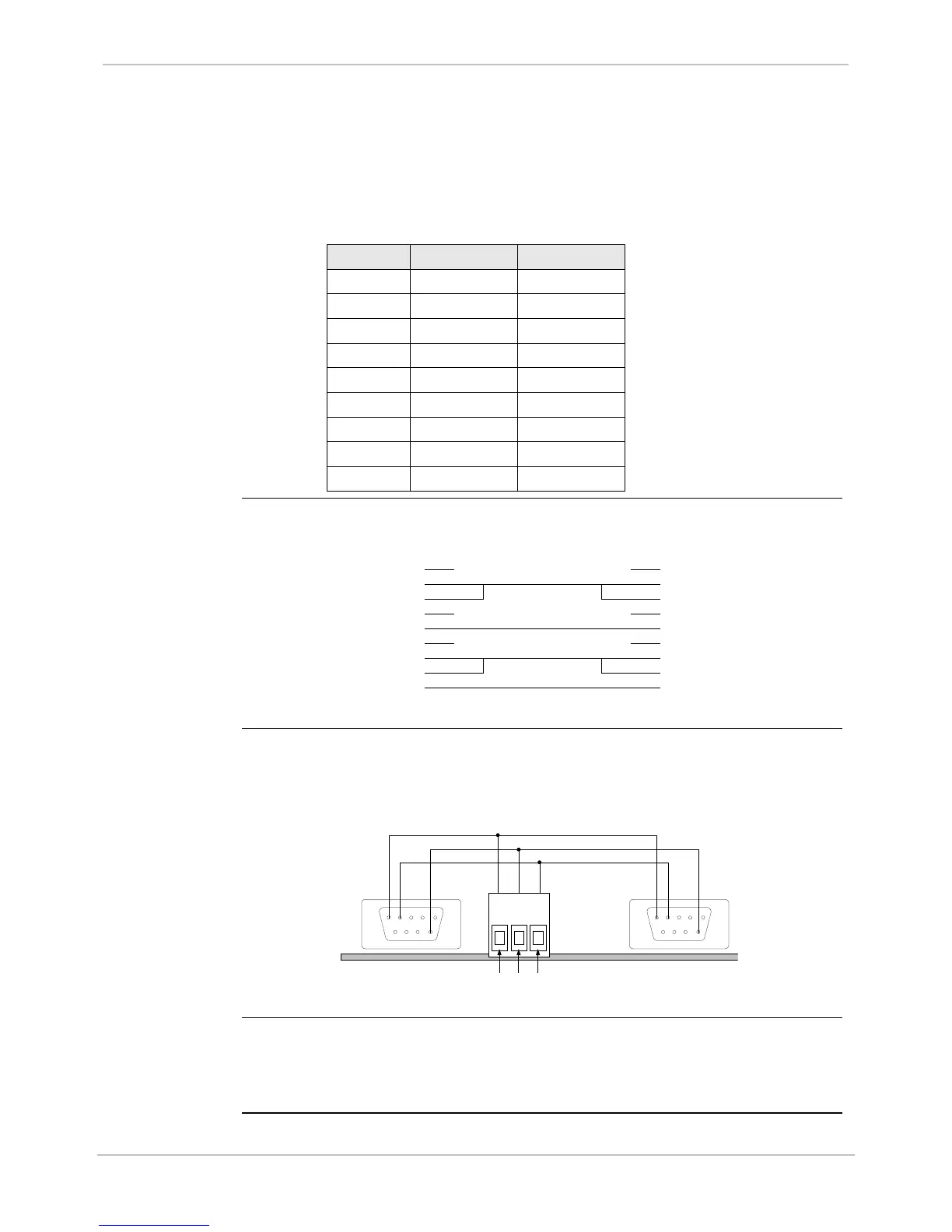
External ±12
Volt Supply
The XCOM card part number 580-0931 is equipped with a 3-pin terminal
(Phoenix) block, where the power for modems attached to the DB-9
connectors can be externally supplied.
1
6
5 4
1
6
5 4
3 2 1
GND -12V +12V
External Power
Note
The power connections are labeled ±12 V, and can be used to provide a
variety of AC or DC voltages.
Use care not to exceed connector or cable specifications.

 Loading...


