DIRECTION 5750007-1EN, REV. 1 LOGIQ E10 BASIC SERVICE MANUAL
Chapter 8 Replacement Procedures 8 - 231
Rear Caster(s) installation
Calibration and adjustments
No calibrations or adjustments are needed after this part replacement.
Verification
Perform the following steps to verify that the product is functioning as intended after this replacement:
1.) Verify that all screws removed earlier have been installed.
2.) Connect cables and Probes removed earlier.
3.) Power up the system to verify that it operates as intended.
Functional Checks
Perform the following functional checks to confirm the system is operational before returning the system
to the customer.
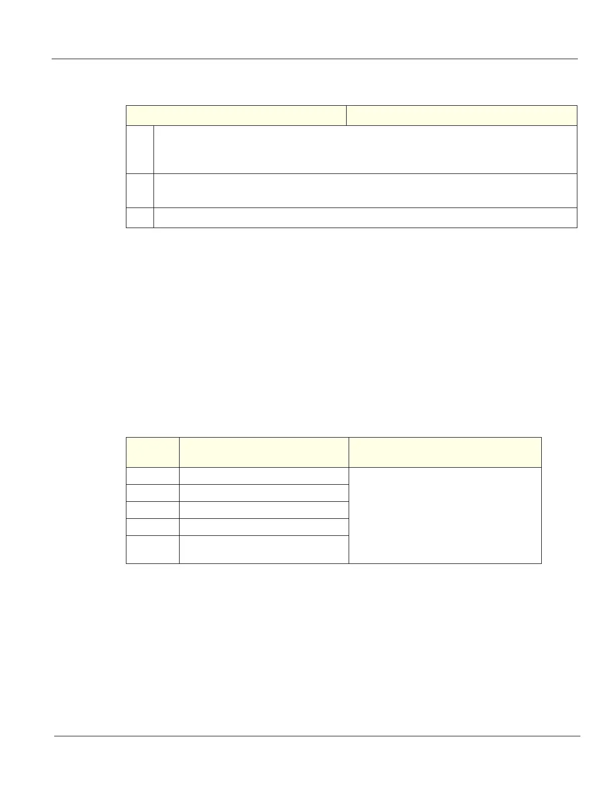
Table 8-251 Rear Caster(s) installation
Steps Corresponding Graphic
1.
Align Caster, mounting it flat and toward the back.
Position Caster so it aligns with the hole for the fixing bolt.
Re-install fixing bolt (M12 X 40 mm). Use a 10 mm hex wrench, torque: 81 Nm (59.7 lbf-ft).
2.
Remove Wooden Wedge and roll LOGIQ E10 off Bevel Edged Board.
To replace the other Rear Caster, repeat all the steps.
3.
Re-install all Covers removed.
Table 8-252 Rear Caster(s) replacement Functional Checks
See:
Section Functional Check Debrief Script
4-2-3 Power ON/Boot Up
LOGIQ E10 Basic Service Manual, Direction
5750007-1EN, Rev. 1. Equipment passed all
required checks and is ready for use.
Required torque was applied.
4-2-7 Probe/Connectors Checks
4-2-5 Top Console checks
4-2-4 Power SHUT DOWN
4-2-6
Brakes and Direction Lock Functional
Checks

 Loading...


