DIRECTION 5750007-1EN, REV. 1 LOGIQ E10 BASIC SERVICE MANUAL
8 - 258 Section 8-11 - Front End Acquisition / Card Cage parts replacement
Front End Card Cage Cover installation
Functional Checks
Perform the following functional checks to confirm the system is operational before returning the system
to the customer.
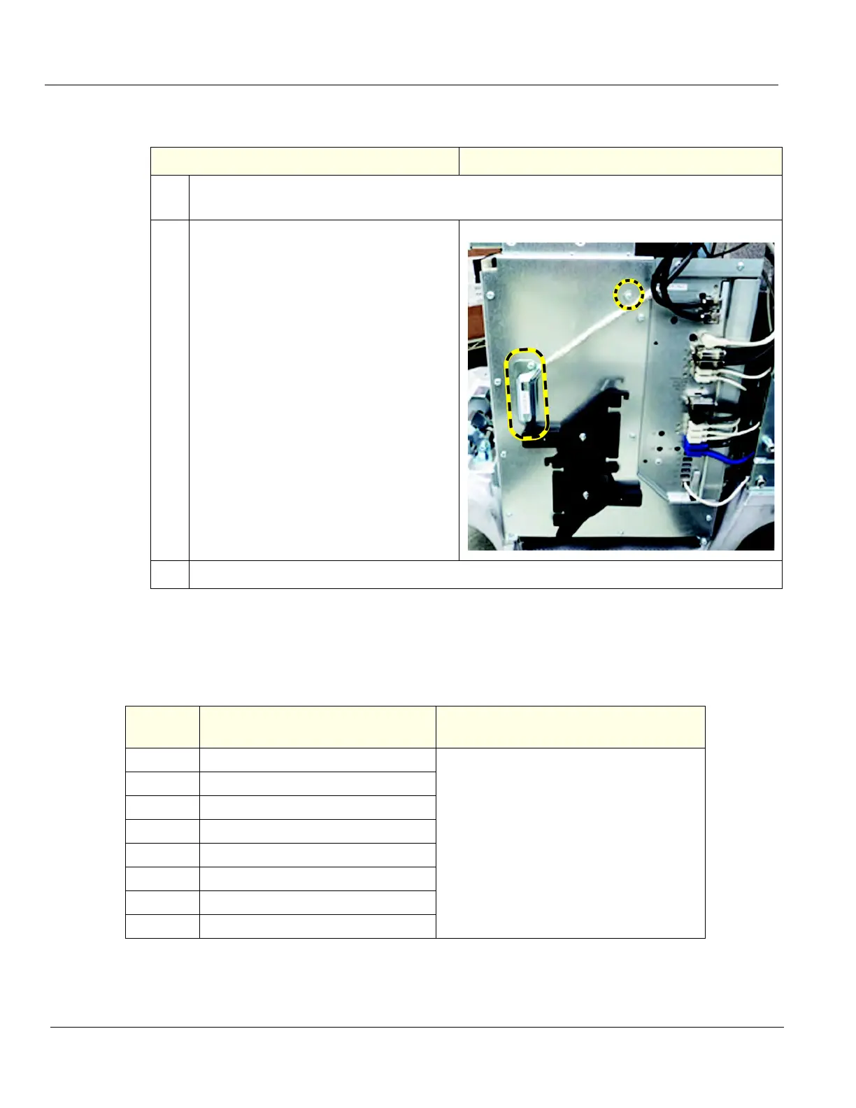
Table 8-278 Front End Card Cage Cover installation
Steps Corresponding Graphic
1. Re-install the Card Cage Cover and secure it with the eight screws removed. Install all the
screws before tightening.
2. Connect the Hi-Pass cable to the GRLY
Board and re-install the EMI Cover, if
present.
Remove the screw from the “P“ clamp to
secure the shielded cable and the clamp to
the Card Cage Cover.
Re-install the Front Plane extraction tools.
3. Re-install all Covers removed.
Table 8-279 Front End Card Cage Cover replacement Functional Checks
See:
Section Functional Check Debrief Script
4-2-3 Power ON/Boot Up
LOGIQ E10 Basic Service Manual, Direction
5750007-1EN, Rev. 1. Leakage Current
measured at (record the value) and meets
allowable limits. Equipment passed all required
checks and is ready for use.
4-2-7 Probe/Connectors Checks
4-2-7 B-Mode Checks
4-2-7 System CFM and PWD Checks
4-2-7 Basic Measurements
10-7-4 Grounding continuity
10-7-5 Chassis leakage current test
4-2-4 Power SHUT DOWN

 Loading...


