2-4 Patient Data Module 2030047-001A
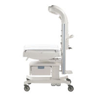
Equipment Overview
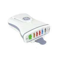
Controls
The power/zero all key has a dual role as a power on and zero all.
Power on — Turns the data acquisition function ON. Power is derived from a
battery or patient monitor. When turned on, the function changes to the zero all
function.
Zero all — Zeros all invasive pressure lines which are open to atmosphere. Each
pressure can also be zeroed, if desired, with a menu option in the pressure menu.
Indicators
Communication
The following LED condition identifies the communication status with a bedside or
transport patient monitor.
No light indicates no communication.
Solid amber indicates an application reset.
Solid green indicates communication.
Flashing amber indicates communication failure.
Alternately flashing with the power LED indicates software transfer.
Power
The following LED condition identifies the power status.
No light indicates no power applied.
Solid amber indicates software booting up.
Solid green indicates powered by AC-derived mains or battery.
Flashing amber indicates approximately five minutes battery power remaining.
Alternately flashing with the communication LED indicates software transfer.
Connector
Patient Data Modules connect to a bedside or transport patient monitor using the host
interface connector. It carries power, communication, and analog output signals to the
display device.
 Loading...