Field Replaceable Units
2030047-001A Patient Data Module 7-11
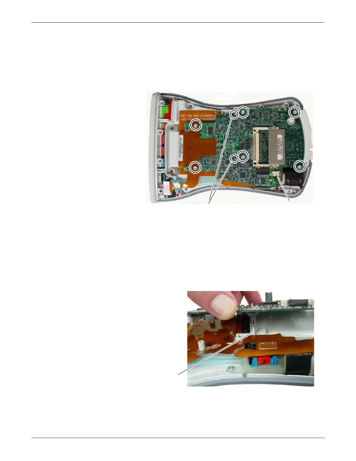
Main board
1. Remove the top housing per above steps.
2. Disconnect the NIBP cable from the connector without pulling on the wires.
465A
3. Remove 6 screws on the main board.
4. Remove the main board.
NOTE
When installing the main board, position it into the alignment pins, (See
figures above and below.) fold the flex material over the top of the board and
hold in place while installing screws.
5. Load new software from the CD included in the Main board FRU kit. Go to
Software Transfer on page 4-9 for instructions.
6. Calibrate analog out. Go to Calibration on page 4-10 for instructions.
NIBP cableAlignment pins
Alignment pin
 Loading...