ADL500 • Quick installation guide - Specifications and connection 15
4.6 Output electrical data
Maximum output voltage U2 ______________ 0.98 x Uln (Uln = AC input voltage)
Maximum output frequency f2 _____________ 300 Hz
The derating factors shown in the table below are applied to the rated DC output by the user. They are not automati-
cally implemented by the drive: Idrive = In x Kx K x K.
Size In Rated output current
(fSw = default)
Pn mot
(Recommended motor power,
fSw = default)
Reduction factor
(fsw = 8 kHz)
IGBT
braking unit
@U
ln =
230Vac
@Uln =
400Vac
@Uln =
460Vac
@Uln =
230Vac
@Uln =
400Vac
@Uln =
460Vac
KV Kt
AdL550
K
t
AdL510
AdL530
K
ALt
(A) (A) (A)
(kW) (kW) (Hp)
(1) (2) (3) (4)
ADL500-...-4, 3ph
1040 9 9 8.1 2 4 5 0.95 1 0.90 1.2
Standard internal
(with external resis-
tor); braking torque
150% MAX
1055 13.5 13.5 12.2 3 5.5 7.5 0.95 1 0.90 1.2
1075 18.5 18.5 16.7 4 7.5 10 0.95 1 0.90 1.2
2110 24.5 24.5 22 5.5 11 15 0.95 1 0.90 1.2
2150 32 32 28.8 7.5 15 20 0.95 1 0.90 1.2
(1) Kv : Derating factor for mains voltage at 460Vac and power supply from AFE200.
(2) K (ADL550): no derating.
(3) K (ADL510/ADL530): 40
(4) K
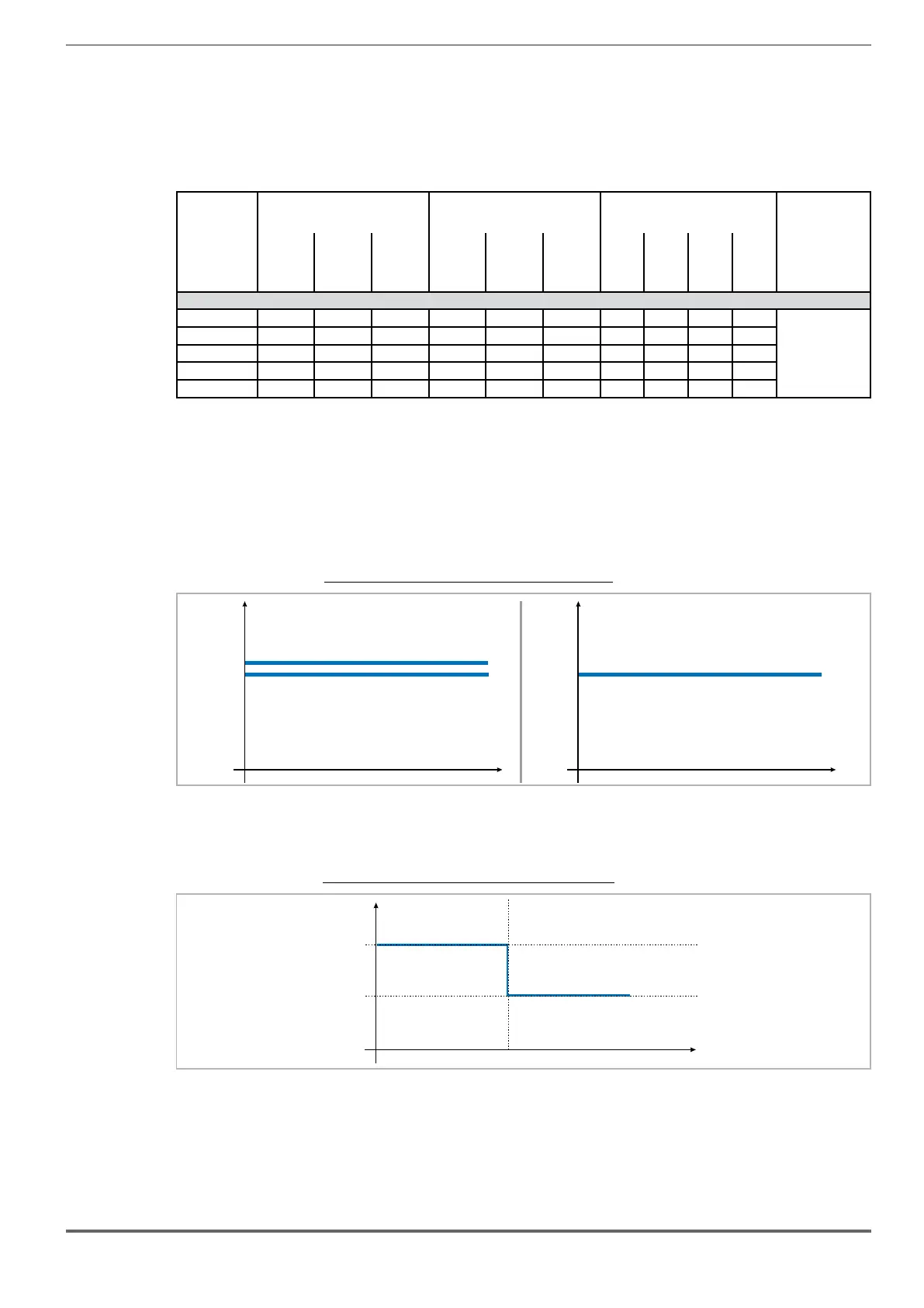
4.6.1 Derating values in overload condition
In overload conditions the output current DO NOT
Figure 4.6.1: Ratio between overload/output frequency (ADL500-...-4)
183
200
OL (% I)
N
183
200
OL (% I)
N
ADL550, sizes 1...3
ADL510/ADL530, sizes 1-3
4.6.2 Derating values for switching frequency
inside
Figure 4.6.2: Ratio between switching frequency/heat sink temperature
5
10
T diss (°C)
F (kHz)
SW
T diss th
 Loading...


