38 ADL500 • Quick installation guide - Specifications and connection
7.3.4 +24V supply connection
Note!
For terminal location see section "7.1 Location and identification of terminals and LEDs" on page 26.
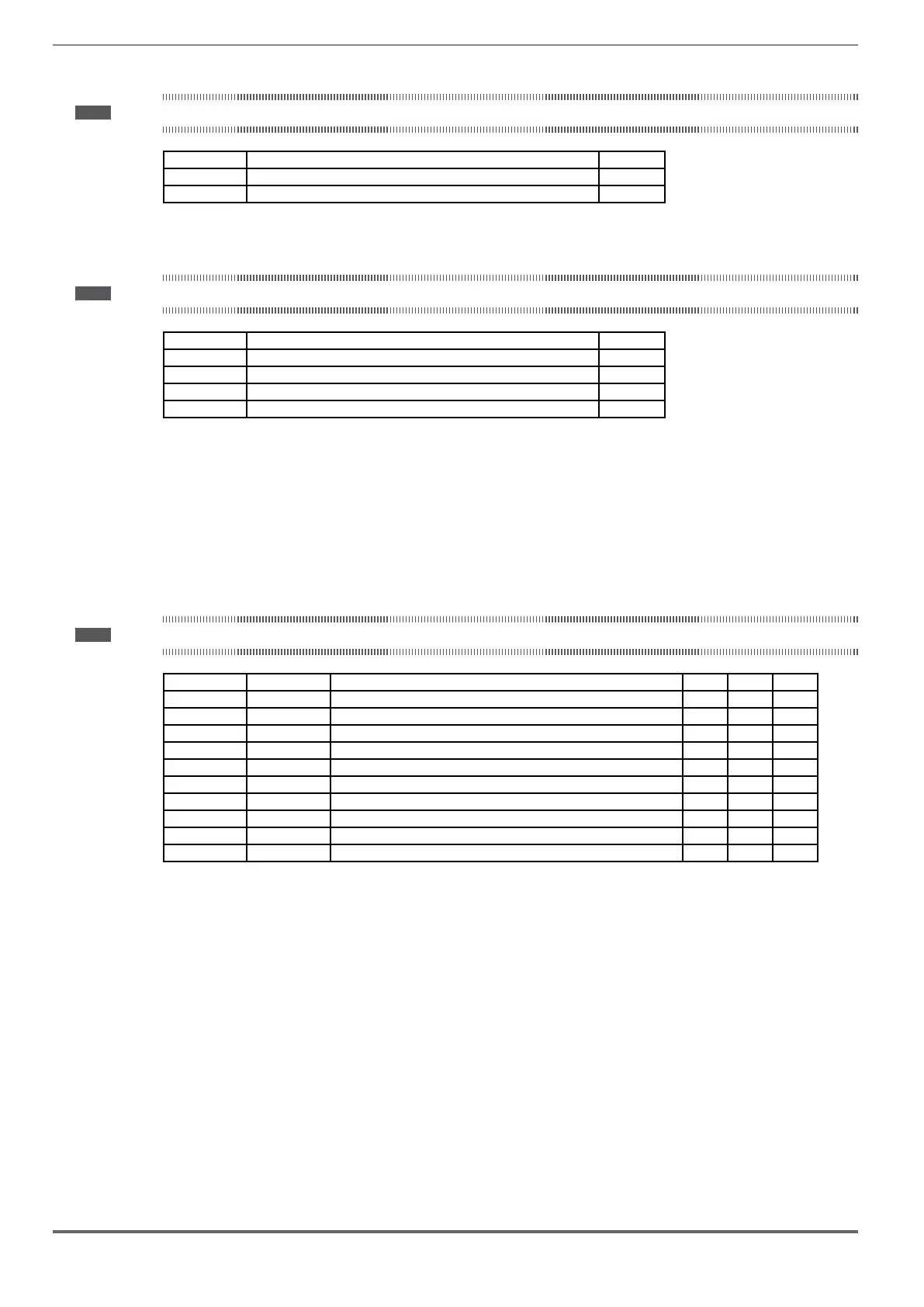
Terminal Description IN/OUT
1 +24
Vdc External power supply of the regulation board IN
2 0
Vdc external power supply reference IN
7.3.5 Safety STO connection (SFTY-STO)
Note!
For terminal location see section "7.1 Location and identification of terminals and LEDs" on page 26.
Terminal Description IN/OUT
EN+ Enable Safety (+) IN
EN- Enable Safety (-) IN
OK1 Safety OK, Output 1 OUT
OK2 Safety OK, Output 2 OUT
The EN+ , EN-, OK1 and OK2 terminals must be connected as shown in the typical connection diagrams in chapter
"7.9 Connection diagrams" on page 42.
Safety management is integrated
The Safety must be enabled to enable the drive.
The drive is disabled if the Safety enable command is removed while it is enabled.
To re-enable the drive, re-enable the Safety then remove and re-send both the Enable and Start commands.
7.3.6 Led
Note!
For terminal location see section "7.1 Location and identification of terminals and LEDs" on page 26.
Led Colour Meaning ADL510 ADL530 ADL550
BRK Yellow Braking Yes Yes Yes
CNT Yellow Contactor closing command status Yes Yes Yes
EN Green Enable Yes Yes Yes
LIM Red Current limit Yes Yes Yes
AL Red Generic alarm Yes Yes Yes
CAN Green CAN 1 - Yes Yes
S-BY Yellow Stand-by - - Yes
UP Green Direction up - - Yes
DOWN Green Direction down - - Yes
PWR Green Power Supply ON - - Yes
 Loading...


