30 ADL500 • Quick installation guide - Specifications and connection
7.3 Regulation section
Note! All terminal strips are extractable. For electrical properties of analog, digital and relay inputs/outputs see section A.2 of the Appendix.
7.3.1 Cable cross-sections
Terminals
Maximum cable cross-section Recommended stripping Tightening torque (min)
(mm
2
) (AWG) (mm) (Nm)
T3, T4, SFTY-STO
0.2 ... 2.5 (1 cable)
0.2 ... 0.75 (2 cables)
26 ... 12
26 ... 19
5 0.4
T1, T2, XER, XE
0.2 ... 1.5 (1 cable)
0.2 ... 0.5 (2 cables)
26 ... 16
26 ... 19
5 0.25
7.3.2 I/O and Relays connection
Note!
For terminal location see section "7.1 Location and identification of terminals and LEDs" on page 26.
T3 terminal – Relays Output
Pin Signal Description Command
Associated parameter
ADL510 ADL530 ADL550
50 RO_4O Relay 4 output (contact N.O., 24
Vdc) 1416, Dig output 4 src Yes Yes Yes
51 RO_4C Common Relay 4 DoopOpen Yes Yes Yes
52 RO_3O Relay 3 output (contact N.O., 24
Vdc) 1414, Dig output 3 src Yes Yes Yes
53 RO_3C Common Relay 3 Run Contactor Yes Yes Yes
54 RO_2O Relay 2 output (contact N.O., 24
Vdc) 1412, Dig output 2 src Yes Yes Yes
55 RO_2C Common Relay 2 Brake Contactor Yes Yes Yes
56 RO_1O Relay 1 output (contact N.O., 24
Vdc) 1410, Dig output 1 src Yes Yes Yes
57 RO_1C Common Relay 1 Drive OK Yes Yes Yes
T1 terminal – Digital inputs
Pin Signal Description Command
Associated parameter
ADL510 ADL530 ADL550
1 DI_8 Digital input 8 Contactor feedback Yes Yes Yes
2 DI_7 Digital input 7 Feedback brake Yes Yes Yes
3 DI_6 Digital input 6 Multispeed 2 Yes Yes Yes
4 DI_5 Digital input 5 Multispeed 1 Yes Yes Yes
5 DI_4 Digital input 4 Multispeed 0 Yes Yes Yes
6 DI_3 Digital input 3 Emergency Yes Yes Yes
7 DI_2 Digital input 2 Start reverse Yes Yes Yes
8 DI_1 Digital input 1 Start forward Yes Yes Yes
T4 terminal – Enable / reference digital inputs and +24V
Pin Signal Description Command
Associated parameter
ADL510 ADL530 ADL550
9 EN_HW Enable digital inputs Yes Yes Yes
10 DI_CM Common reference digital inputs Yes Yes Yes
11 0V24_OUT Ground reference output voltage Yes Yes Yes
12 +24V_OUT +24
Vdc output voltage power supply Yes Yes Yes
T2 terminal – Analog input and motor PTC
Pin Signal Description Command
Associated parameter
ADL510 ADL530 ADL550
1 MOT- PTC reference - Yes Yes
2 MOT+ PTC signal - Yes Yes
3 AI_1P Analog input 1 Yes Yes Yes
4 AI_1N Common reference analog input Yes Yes Yes
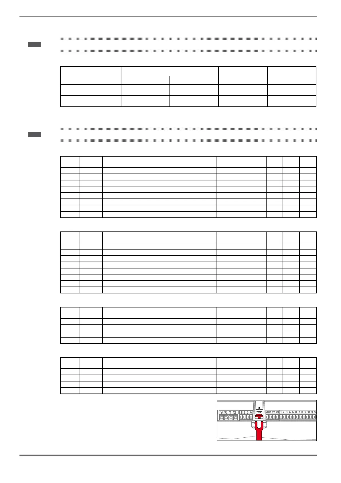
T2 terminal shield connection (recommended)
1) remove the front cover (unscrew the 4 M3 screws with a Ph2 Phillips
screwdriver, see section "A.1.1 - Installation" on page 87),
2) attach a spade lug connector to the signal cable shield,
3) loosen the ground screw on the metal frame, insert the fork and then
screw it down.
T4 T2
XER XE
 Loading...


