ADL500 • Quick installation guide - Specifications and connection 19
5.3 AC output chokes
The ADL500
The latter usually have a higher isolation rating to better withstand PWM voltage Examples of reference regulations
inverter. For standard motors, especially with long cable runs (typically over 100 m) an output choke may be necessary
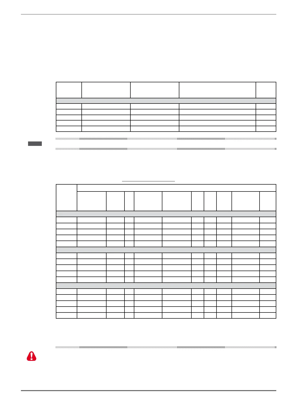
The range of recommended chokes are listed in the following table. The rated current of the chokes should be approx.
waveform.
Size Model Code
Dimensions:
Width x Height x Depth
mm [inches]
Weight
kg [lbs]
ADL5...-...-4, 3ph
1040 LU3-005 S7FG3 180 x 170 x 110 [7.1 x 6.7 x 4.3] 5.8 [12.8]
1055 LU3-005 S7FG3 180 x 170 x 110 [7.1 x 6.7 x 4.3] 5.8 [12.8]
1075 LU3-005 S7FG3 180 x 170 x 110 [7.1 x 6.7 x 4.3] 5.8 [12.8]
2110 LU3-011 S7FG4 180 x 180 x 130 [7.1 x 7.1 x 5.1] 8 [17.6]
2150 LU3-015 S7FH2 180 x 160 x 170 [7.1 x 6.3 x 6.7] 7.5 [16.5]
Note ! With the inverter operated at the rated current and a frequency of 50 Hz, the output chokes cause a voltage drop of approx. 2% of the output voltage.
5.4 External braking resistors
Recommended combinations for use with internal braking unit.
Table 5.4.1: Recommended combination
Size
List and technical data of standard external resistors
Resistor type Code Q.ty
Max. overload,
1" - service 10%
E
br (kJ)
Max. overload,
30" - service 25%
Ebr (kJ)
Pnbr
(W)
Rbr
(Ω)
Housing
Dimensions:
Width x Height x
Depth (mm)
Weight
(kg)
ADL5...-...-4, 3ph - LOW DEMAND
1040 RFPR 750 D 68R S8SZ3 1 7.5 38 425 68 IP44 245 x 75 x 100 2.7
1055 RFPR 750 D 68R S8SZ3 1 7.5 38 425 68 IP44 245 x 75 x 100 2.7
1075 RFPR 1200 D 49R S8SZ4 1 7.5 28 470 49 IP44 310 x 75 x 100 4.2
2110 RFPR 1900 D 28R S8SZ5 1 12 43 550 28 IP44 365 x 75 x 100 4.2
2150 RFPR 1900 D 28R S8SZ5 1 12 43 550 28 IP44 365 x 75 x 100 4.2
ADL5...-...-4, 3ph - MID DEMAND
1040 1650 68
1055 1650 68
1075 2250 49
2110 3300 28
2150 4500 28
ADL5...-...-4, 3ph - HIGH DEMAND
1040 2750 68
1055 2750 68
1075 3750 49
2110 5500 28
2150 7500 28
P Braking resistor rated power
R Braking resistor ohmic value
E Maximum energy that can be dissipated on the resistor
Braking resistors may be subject to unexpected overloads due to faults.
Resistors MUST be protected using thermal cutouts. These devices must not interrupt the circuit in which the resistor is
protection contact, this must be used together with that of the thermal cutout.
A la suite de pannes, les résistances de freinage peuvent être sujettes à des surcharges imprévues. La protection des
résistances au moyen de dispositifs de protection thermique est absolument capitale. Ces dispositifs ne doivent pas inter
-
rompre le circuit qui abrite la résistance, mais leur contact auxiliaire doit couper l’alimentation du côté puissance du drive.
Warning!
 Loading...


