ADL500 • Quick installation guide - Specifications and connection 45
7.9.3 Emergency connection diagram
To use this type of connection reference should be made to the safety and installation instructions in the ADL550 /
https://www.gefran.com/en/
download/5435/attachment/en).
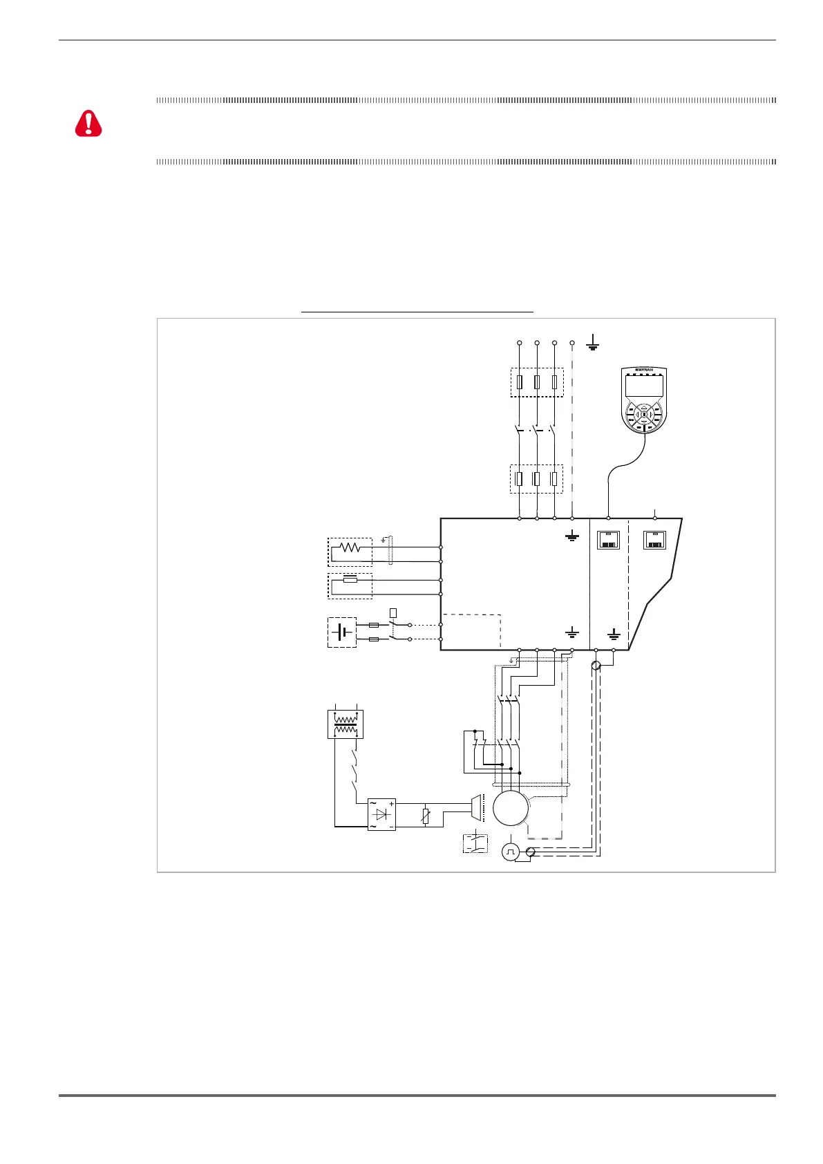
7.9.3.1 Emergency connection diagram with EMS module (ADL5.0-...-EMS modes)
In the event of a three-phase power failure, the system manages motor movement in an emergency condition through
an external battery connected to the EMS module built into the ADL510/530/550-...-EMS models.
The battery contactor can be kept closed to reduce the cabin stop time.
Figure 7.9.5: Emergency connection diagram with EMS module
1
2
K1M
3
4
5
6
M
3
~
DC CHOKE
L2
(ADL550: 4 to 22kW)
ADL550-...-EMS
ADL530-...-EMS
ADL510-...-EMS
U1
V1 W1
U2
V2
W2
L1 L2 L3
KEYPAD
ETH-PC
T1 T2 T3
PE
PE
D
C
BR1
EM
BREAKING
RESISTOR
BR2
BRAKE
K2M
K3M
BR
TRAFO
3 Phase Mains
FBR
5
6
3
4
1
2
K2M
5
6
3
4
1
2
K3M
XE
XER
PE
C1
OPTIONAL
AC CHOKE
L1
OPTIONAL
F1
Emergency
Mode
Supplier
Battery Pack
(Optional)
+
_
KB
Warning!
 Loading...


