Section 2 Engine DC Control System
10 Diagnostic Repair Manual
Operational Analysis (Older Units)
Circuit Condition - Rest
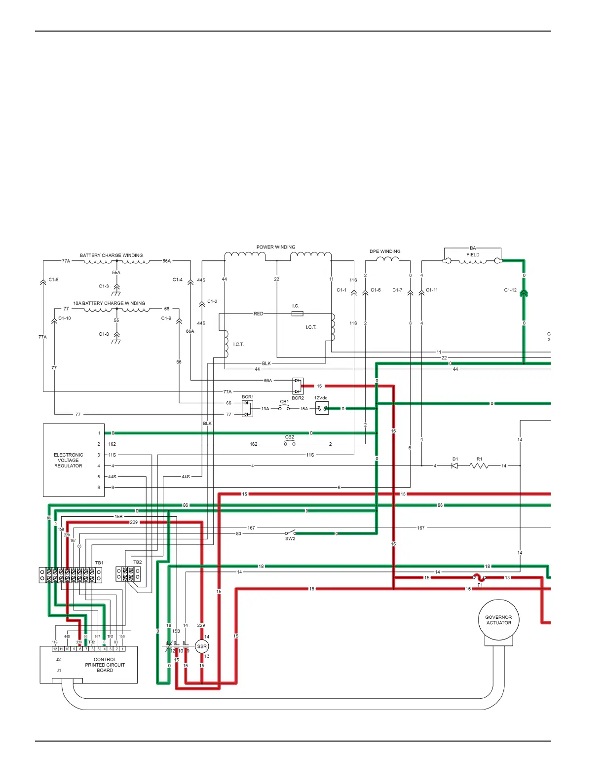
Battery voltage is supplied to components of the control system from the unit battery via the red battery cable
connected to the contacts of the starter contactor (SC), wire 13, a 10 Amp fuse (F1), and wire 15.
Wire 13 is unfused battery supply voltage and is connected to the contacts of the starter contactor relay (SCR).
Wire 15 is 12 VDC fused battery supply voltage to the SCR. DC voltage flows through the SCR coil and exits the coil as
wire 17. Wire 17 is connected to the start-run-stop switch (SW1) and is held open to ground. Current does not flow
through the circuit and the SCR is de-energized.
Wire 15 is 12 VDC fused battery voltage supplied to the SW1 and is held open to wire 167.
Wire 15 is 12 VDC fused battery voltage to the start stop relay (SSR). DC voltage flows through the SSR coil and exits
as wire 229. Wire 229 will be 12 VDC held open from ground by the printed circuit board. Current does not flow through
the circuit and the SSR is de-energized.

 Loading...


