Section 4 AC Diagnostic Tests
Diagnostic Repair Manual 61
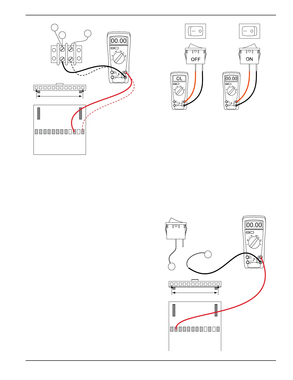
Figure 4-57. Check Wires 11S & 44S or 11S & 22S
6. Connect the other meter test lead to wire 11S at
terminal block 2 (TB2).
a. Continuity should be measured.
NOTE: Where terminal block is not present, place meter
test lead on the wire at the termination point. If
necessary, use a small paper clip to probe beside the
wire so as not to damage the terminal in the connector.
Results
1. If Continuity was not measured, repair or replace
the wire harness.
2. If Continuity was measured, refer back to the flow
chart.
Test 52 – Check Idle Control Switch
(SW2)
Procedure
1. Set DMM to measure resistance.
2. Disconnect wire 0 and wire 83 from the idle control
switch (SW2).
3. See Figure 4-58. Connect meter test leads across
both terminals of SW2.
a. In the OFF position Infinity should be
measured.
b. In the ON position Continuity should be
measured.
Results
1. If the switch fails step 3 replace it.
2. If the switch is good refer back to the flow chart.
Figure 4-58. Check Idle Control Switch (SW2)
Test 53 – Check Idle Control Wiring
Procedure
1. Set DMM to measure resistance.
2. Disconnect wire 0 from the Idle Control Switch
(SW2).
3. Connect one meter test lead to wire 0.
4. Connect the other meter test lead to frame ground.
Continuity should be measured.
a. If continuity is not measured repair or replace
wire 0 between SW2 and the ground terminal.
5. Disconnect wire 83 from SW2.
6. Disconnect the J2 connector from the printed
circuit board.
Figure 4-59. Check Idle Control Wiring
J2 HARNESS CONNECTOR
J2-1 J2-12
TB2
22S NEWER
STEP 2
STEP 3
STEP 2
STEP 3
11S
44S OLDER
J2 HARNESS CONNECTOR
SW2
J2-1 J2-12
0
83

 Loading...


