Section 4 AC Diagnostic Tests
54 Diagnostic Repair Manual
7. If voltage was not measured in step 3 connect one
meter test lead to wire 229 removed from the SSR.
8. Connect the other meter test lead to wire 229 at the
terminal block 1 (TB1). Continuity should be
measured.
a. If continuity is not measured repair or replace
wire 229 between SSR and TB1.
NOTE: Where terminal block is not present, place meter
test lead on the wire at the termination point. If
necessary, use a small paper clip to probe beside the
wire so as not to damage the terminal in the connector.
9. Remove the J2 connector the printed circuit board.
10. Connect one meter test lead to pin location J2-8
(wire 229)
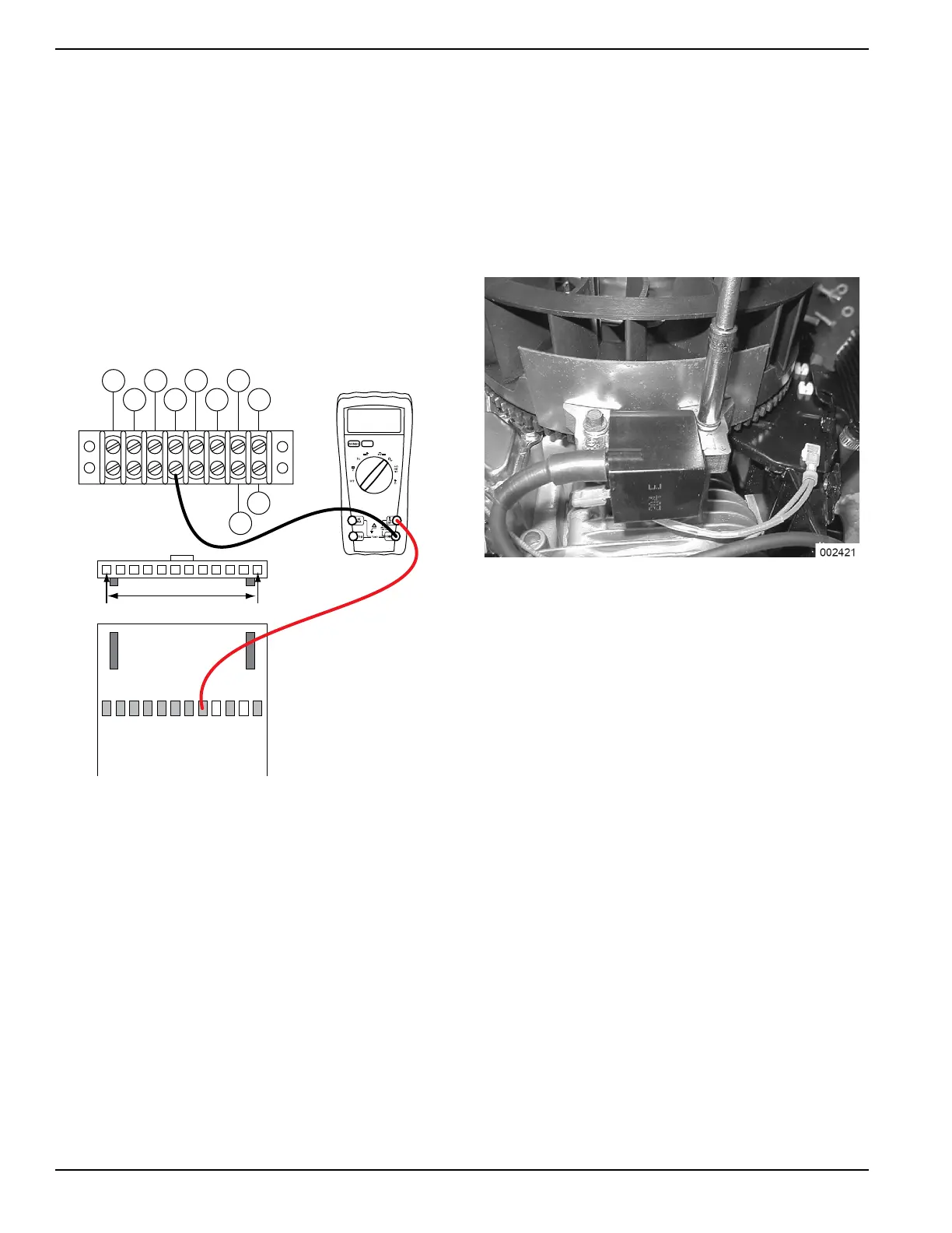
Figure 4-47. Testing Wire 229 Between J2 Connector
and Terminal Block 1 (TB1)
11. See Figure 4-47. Connect the other meter test
lead to wire 229 at TB1. Continuity should be
measured.
a. If continuity is not measured repair or replace
wire 229 between the J2 connector and TB1.
Results
1. If step 5 passed refer to Flow Chart.
2. If step 5 failed and step 11 passed replace the
printed circuit board.
Test 35 – Check and Adjust Ignition
Magnetos
Procedure
1. See Figure 4-48. Rotate the flywheel until the
magnet is under the module (armature)
laminations.
2. Place a 0.008-0.012 inch (0.20-0.30mm) thickness
gauge between the flywheel magnet and the
module laminations.
Figure 4-48. Setting Ignition Magneto Air Gap
3. Loosen the mounting screws and let the magnet
pull the magneto down against the thickness
gauge.
4. Tighten both mounting screws.
5. To remove the thickness gauge, rotate the
flywheel.
6. Repeat the above procedure for the second
magneto.
7. Repeat Test 29 – Check Ignition Spark and
check for spark across the spark tester gap.
8. If air gap was not out of adjustment, remove engine
ground harness from magnetos. Repeat Test 29 –
Check Ignition Spark. If sparking now occurs
replace engine ground harness.
9. Check the flywheel magnet by holding a
screwdriver at the extreme end of its handle and
with its point down. When the tip of the screwdriver
is moved to within 3/4 inch (19 mm) of the magnet,
the blade should be pulled in against the magnet.
10. Check the flywheel key. The flywheel’s taper is
locked on the crankshaft taper by the torque of the
flywheel nut. A keyway is provided for alignment
only and theoretically carries no load.
NOTE: If the flywheel key becomes sheared or even
partially sheared, ignition timing can change. Incorrect
timing can result in hard starting or failure to start.
TB1
J2 HARNESS CONNECTOR
00.00
86 15B
167
BLK
0 229
83
BLK
TR2
TR1
J2-1 J2-12

 Loading...


