Section 4 AC Diagnostic Tests
48 Diagnostic Repair Manual
Test 23 – Check Voltage At Starter
Contactor (SC)
Procedure
1. Set DMM to measure DC voltage.
2. Disconnect wire 16 from the starter contactor
located on the starter motor.
3. Connect the positive meter test lead to wire 16
removed in step 2.
4. Connect the negative meter test lead to frame
ground.
5. Set the start-run-stop switch to START.
a. 12 VDC should be measured.
6. Connect wire 16 to the starter motor.
Results
Refer back to flow chart.
Test 24 – Check Starter Contactor (SC)
Procedure
1. Carefully inspect the starter motor cable that runs
from the battery to the starter motor.
a. Cable connections should be clean and tight.
b. If connections are dirty or corroded, remove
cable and clean cable terminals and studs.
c. Replace any cable that is defective or badly
corroded.
2. Set DMM to measure DC voltage.
3. See Figure 4-31, Test Point 1. Connect the
positive (+) meter test lead to the starter contactor
stud that the battery cable is connected to.
4. Connect the negative (-) meter test lead to a clean
frame ground.
a. Battery voltage should be measured.
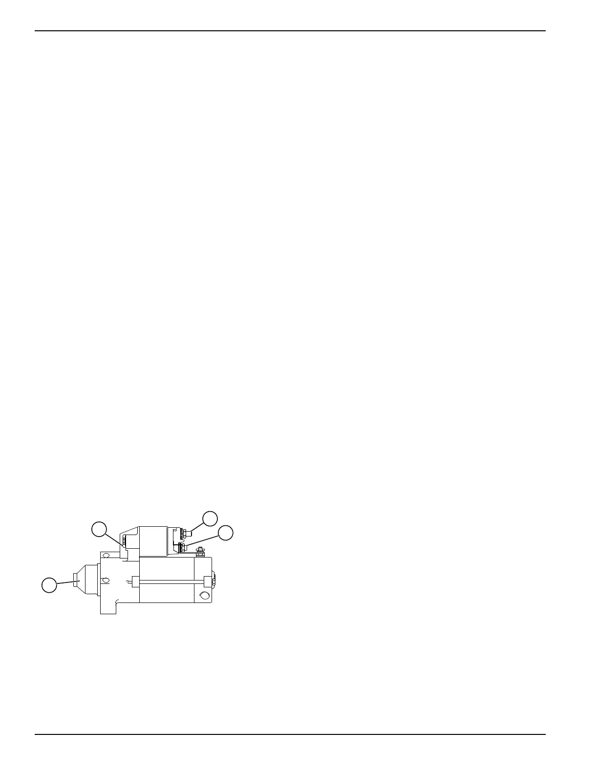
Figure 4-31. The Starter Contactor (SC)
5. Set DMM to measure DC voltage.
6. See Figure 4-31, Test Point 2. Connect the
positive (+) meter test lead to the starter contactor
stud that has the small jumper wire connected to
the starter.
7. Connect the negative (-) meter test lead to a clean
frame ground.
8. Set the start-run-stop switch to START.
a. Battery voltage should be measured.
Results
1. If battery voltage was not measured in step 1,
repeat Test 22.
2. If battery voltage was measured in step 4a, but not
in step 8a, replace the starter contactor.
3. If battery voltage was measured in step 8a but the
engine still does not crank, refer back to the flow
chart.
Test 25 – Check Starter Motor
Conditions Affecting Starter Motor Performance
1. A binding or seizing condition in the starter motor
bearings.
2. A shorted, open or grounded armature.
• Shorted, armature (wire insulation worn and wires
touching one another). Will be indicated by low or
no RPM.
• Open armature (wire broken) will be indicated by
low or no RPM and excessive current draw.
• Grounded armature (wire insulation worn and wire
touching armature lamination or shaft). Will be
indicated by excessive current draw or no RPM.
3. A defective starter motor switch.
4. Broken, damaged or weak magnets.
5. Starter drive dirty or binding.
Procedure
The battery should be fully charged and checked prior to
this test.
Set DMM to measure DC voltage (12 VDC).
Connect the meter positive (+) test lead to the starter
contactor stud which has the small jumper wire
connected to the starter. Connect the common (-) test
lead to the starter motor frame.
Set the start-run-stop switch to START and observe the
meter. Meter should indicate battery voltage, starter
motor should operate and engine should crank.
Results
1. If battery voltage is indicated on the meter but
starter motor did not operate, remove and bench
test the starter motor.
2. If battery voltage was indicated and the starter
motor tried to engage (pinion engaged), but engine
did not crank, check for mechanical binding of the
engine or rotor.
A. Starter Contactor
B. Starter Motor
C. Test Point 1
D. Test Point 2
A
B
D
C
004652

 Loading...


