Section 4 AC Diagnostic Tests
Diagnostic Repair Manual 45
Test 15 – Check Load Voltage and
Frequency
Procedure
Perform this test in the same manner as Test 1, but apply
a load to the generator equal to its rated capacity. With
load applied check voltage and frequency.
Frequency should not drop below about 59 Hertz with the
load applied.
Voltage should not drop below about 235 VAC with load
applied.
Results
1. If voltage and/or frequency drop excessively when
the load is applied, go to Test 16.
2. If load voltage and frequency are within limits, end
tests.
Test 16 – Check Load Watts and
Amperage
Procedure
Add up the wattages or amperages of all loads powered
by the generator at one time. If desired, a clamp-on
ammeter may be used to measure current flow.
Results
1. If the unit is overloaded, reduce the load.
2. If load is within limits, but frequency and voltage
still drop excessively, refer back to flow chart.
Test 17 – Check Battery Charge Output
Procedure
1. Disconnect wire 15 (center terminal) from battery
charge rectifier 2 (BCR2), which is located under
BCR1. They are stacked.
See Control Panel Component Identification for BCR1
and BCR2 location.
Figure 4-24. Testing BCR2
2. Set DMM to measure DC Amps.
a. Connect the positive (+) test lead to the center
terminal of the battery charge rectifier.
b. Connect the negative (-) test lead to wire 15
disconnected in step 1.
3. Start the generator.
a. The amp reading on the meter should be
approximately 0.6 Amps.
b. Apply full load to the generator.
c. The amp reading should increase to
approximately 2 Amps.
Results
1.
If amperage was measured between 0.6 to 2 Amps
in step 2 and step 3, the charging system is working.
2. If no amperage was measured, check the meter
fuses and verify the functioning of the meter. If
meter is good and no current is measured refer to
flow chart.
Test 18 – Check 10 Amp Battery
Charge Output
Procedure
NOTE: The battery charge cable must be connected to
the 12 VDC panel receptacle and be charging a separate
battery to perform this test.
1. Disconnect wire 13A (center terminal) from battery
charge rectifier 1 (BCR1), which is located on top
of BCR2. See Control Panel Component
Identification for BCR1 and BCR2 location.
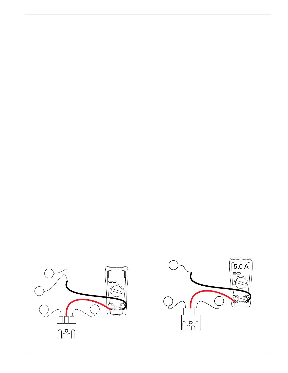
2. See Figure 4-25. Set DMM to measure DC
Amperage.
a. Connect the positive (+) test lead to the center
terminal of the battery charge rectifier.
b. Connect the negative (-) test lead to wire 13A
previously disconnected.
Figure 4-25. Testing BCR1
66A
15
BCR2
77A
15
2.0 A
004613

 Loading...


