Section 4 AC Diagnostic Tests
Diagnostic Repair Manual 55
Results
If sparking still does not occur after adjusting the
armature air gap, testing the ground wires and
performing the basic flywheel test, replace the ignition
magneto(s).
Test 36 – Test Fuel Shutoff Solenoid
(FSS)
Procedure
1. Disconnect wire 16 from the starter contactor (SC)
located on the starter motor.
2. Remove the air cleaner cover.
3. Set the start-run-stop switch (SW1) to STOP then
to START. When SW1 is activated a click should be
heard and or activation of the fuel shutoff solenoid
should be felt, indicating that the fuel shutoff
solenoid is functioning.
Results
Refer to flow chart.
Test 37 –Test Fuel Shutoff Solenoid
Voltage
Procedure
1. Set DMM to measure DC voltage.
2. Disconnect the two pin connector from the fuel
shutoff solenoid (FSS).
3. Connect the positive meter test lead to the red
wire.
4. Connect the negative meter test lead to the black
wire.
5. Set the start-run-stop switch (SW1) to START.
During cranking, 12 VDC should be measured.
a. If DC voltage is not measured continue testing.
6. Set DMM to measure resistance.
7. Connect one meter test lead to the black wire.
8. Connect the other meter test lead to frame ground.
Continuity should be measured.
a. If continuity is not measured repair or replace
the black ground wire or correct poor ground
connection.
9. Set DMM to measure DC voltage.
10. See Figure 4-53. Remove wire 14 from the Start
Stop Relay (SSR).
11. Connect the positive meter test lead to the terminal
of the SSR that wire 14 was just removed.
12. Connect the negative meter test lead to frame
ground.
13. Set the start-run-stop switch (SW1) to START. 12
VDC should be measured.
a. If 12 VDC is measured repair or replace wire
14 between the SSR and resistor R1 or
between resistor R1 and the FSS.
Results
Refer to flow chart.
Test 38 – Check Fuel Pump
Procedure
1. Remove the fuel line from the fuel filter on the inlet
side of the carburetor. Use a suitable container to
catch fuel.
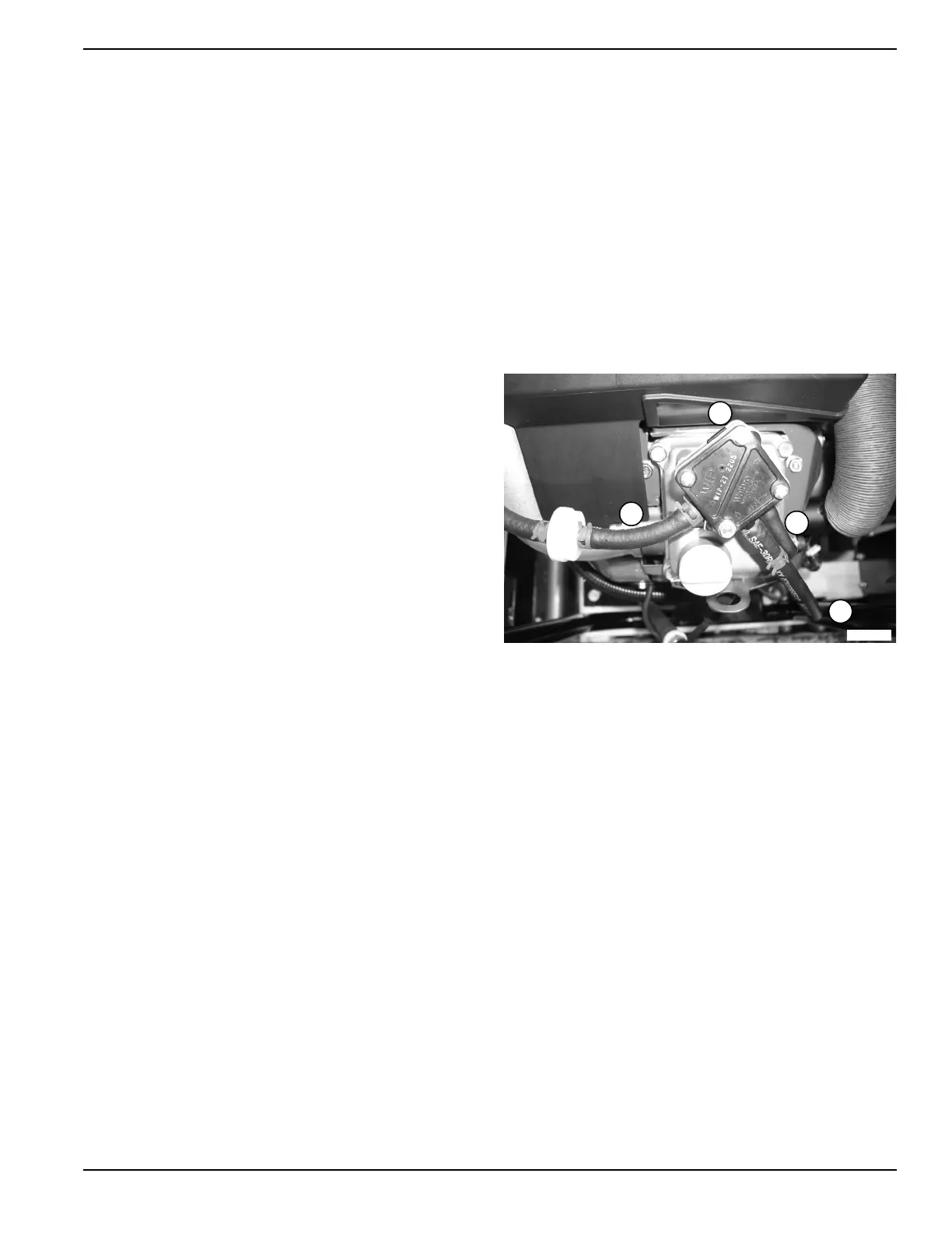
Figure 4-49. Fuel Pump and Fuel Lines
2. Crank the engine. Fuel should flow from the fuel
line.
a. If fuel does not flow, verify that fuel is available
to the pump.
b. If fuel is available to the pump inspect the fuel
filter, pulse line, and or replace the fuel pump.
Results
Refer to flow chart.
Test 39 – Check Carburetion
Procedure
Before making a carburetion check, verify the fuel supply
tank has an ample supply of fresh, clean gasoline.
Check that all shutoff valves are open and fuel flows
freely through the fuel line.
Verify the choke operates properly.
A. Fuel pump
B. Fuel to carburetor
C. Pulse line
D. Fuel from tank
C
D
A
B
004661

 Loading...


