Section 4 AC Diagnostic Tests
Diagnostic Repair Manual 59
a. Resistance measured should be approximately
100 ohms.
Results
1. If the SSR measures continuity or zero resistance it
is shorted to ground and should be replaced.
2. If the SSR resistance is correct refer to flow chart.
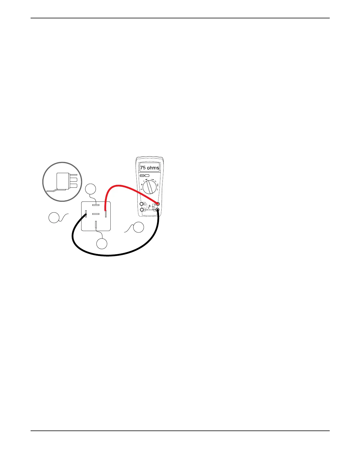
Test 44 – Test Starter Contactor Relay
(SCR)
Procedure
1. Set DMM to measure resistance.
2. See Figure 4-54. Disconnect wire 15 and wire 17
from the starter contactor relay (SCR).
3. Connect one meter test lead to the terminal that
wire 15 was removed from.
Figure 4-54. Testing Starter Contactor Relay (SCR)
4. Connect the other meter test lead to the terminal
that wire 17 was removed from.
a. Resistance measured should be approximately
75 ohms.
Results
1. If the SCR measures continuity or zero resistance
it is shorted to ground and should be replaced.
2. If the SCR resistance is correct refer to flow chart.
Test 45 – Check Wire 15 Circuit
Procedure
1. Set DMM to measure resistance.
2. Remove fuse F1.
3. Disconnect wire 15 from the start stop relay (SSR).
NOTE: See Figure 4-53. wire 15 connects to the SSR at
three terminals.
4. Disconnect wire 15 from the starter contactor (SC).
5. Disconnect wire 15 from the start-run-stop switch
(SW1).
6. Disconnect wire 15 from the battery charge rectifier
2 (BCR2).
7. Remove wire 15 from the fuse holder (F1).
8. Connect one meter test lead to wire 15 just
removed.
9. Connect the other meter test lead to frame ground.
10. Infinity should be measured.
Results
If Infinity was not measured a short on wire 15 to ground
exists. Inspect each wire 15 for a shorted condition.
Repair or replace as needed.
Test 46 – Check Wire 14 Circuit
Procedure
1. Set DMM to measure resistance.
2. Disconnect wire 14 from the start stop relay (SSR).
3.
Connect one meter test lead to wire 14 previously
removed. Connect the other meter test lead to frame
ground. Approximately 38 ohms should be measured.
Results
Refer back to flow chart.
Test 47 – Check Fuel Shutoff Solenoid
(FSS)
Procedure
1. Set DMM to measure resistance.
2. Disconnect the plug from the fuel shutoff solenoid
(FSS).
3. Connect one meter test lead to one pin on the
FSS.
4. Connect the other meter test lead to the remaining
pin on the FSS.
a. Approximately 38 ohms should be measured.
5. Connect one meter test lead to one pin on the
FSS.
6. Connect the other meter test lead to frame ground.
a. Infinity should be measured.
Results
1. If continuity or zero was measured in step 3 or step
6 replace the FSS.
2. (Units without hour meter) If correct resistance was
measured refer to flow chart, repair or replace wire
14 between the FSS and resistor R1.
3. (Units with hour meter) Refer back to flow chart.

 Loading...


