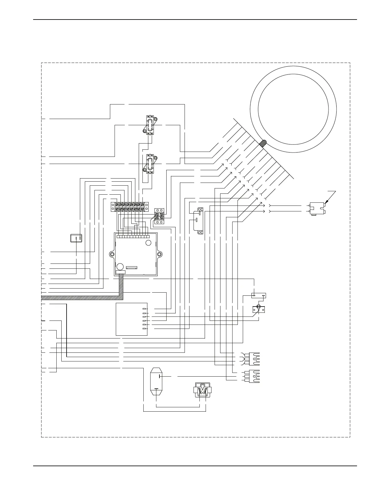
Wiring Diagram 17.5 kW – Drawing No. 0G0731
4
0
CLOSEST TO BEARING
STATOR
66
REGULATOR
VOLTAGE
12Vdc OUTLET
RESET BKR
10A AUTO
162
6
4
0
162
11S
22S
SCR - STARTER CONTACTOR RELAY
TB1, TB2 - TERMINAL BLOCK
SSR - START / STOP RELAY
SP2 - SPARK PLUG, CYL. 2
SP1 - SPARK PLUG, CYL. 1
SM - STARTER MOTOR
SC - STARTER CONTACTOR
R1 - 25 OHM, 25W RESISTOR
IM2 - IGNITION MODULE, CYL. 2
FSS - FUEL SHUT OFF SOLENOID
CB1 - 6AMP AUTO RESET BREAKER
LOP - LOW OIL PRESSURE
IM1 - IGNITION MODULE, CYL. 1
GND - GROUND BAR
F1 - 10A FUSE
D2 - 600V 12A DIODE
D - ENGINE SHUTDOWN DIODE
BA - BRUSH ASSEMBLY
LEGEND
RECTIFIER
CHARGE
BATTERY
CHARGE
BATTERY
RECTIFIER
D2
R1
22
ENGINE SHUTDOWN P.C.B.
ELECTRONIC GOVERNOR /
CONTROL
SWITCH
IDLE
ON/OFF
22S
55
11S 55A
TB2
TB1
BLK
CB1
BLK
RED
1
2
11
44
IDLE CONTROL
TRANSFORMERS
8
PIN #
12
10
11
9
BA
77A
5
7
6
66A
4
3
2
66
55
77
6
55A
22S
11S
22
77
4
0
77A
66A
77
66 6
55
2
55A
22S
11S
44
11
11
22
22
11
44 44
83
167
229
15B
0
86
86
15B
229
14
167
0
86
0
14
0
0
15
15
0
55A
55
0
14
83
167
229
15B
0
13A
15
15
15
15
55A
55
0
14
66A
77A
4
66
77A4
066A 6
77
0
15A
13A
0
15A0
14
0
14
14
14
162
55
55A
J1
J2
1012 11 896745231

 Loading...


