Diagnostic Repair Manual 35
Section 4 AC Diagnostic Tests
Introduction
This section familiarizes the service technician with
acceptable procedures for the testing and evaluation of
various problems that can occur on portable generators.
Use this section in conjunction with the Troubleshooting
Flow Charts. The numbered tests in this section
correspond with those of the flow charts.
These test procedures require a basic knowledge of
electricity and electrical safety, hand tool skills, and use
of multimeters.
Some test procedures in this section require the use of
specialized test equipment, meters or tools. Most tests
can be performed with a digital multimeter (DMM). An AC
frequency meter is required where frequency readings
must be taken. To measure AC loads it is acceptable to
use a clamp-on ammeter.
Testing and troubleshooting methods covered in this
manual are not exhaustive. No attempt has been made to
discuss, evaluate and advise the home standby service
trade of all conceivable ways in which service and trouble
diagnosis must be performed. Any test method not
recommended herein must be deemed safe for
personnel and equipment.
Safety
Service personnel who work on this equipment should be
aware of the dangers of such equipment. Lethal voltages
are present and can kill or cause serious injury. Gaseous
fuels are highly explosive and can ignite by the slightest
spark. Engine exhaust gases contain deadly carbon
monoxide gas that can cause unconsciousness or even
death. Contact with moving parts can cause serious
injury.
When working on this equipment, use common sense
and remain alert at all times. Never work on this
equipment while you are physically or mentally fatigued.
If you do not understand a component, device or system,
do not work on it.
Important Note Concerning
Connectors
A number of the tests require the use of a multimeter and
a set of test probes.
It is very easy to damage the female pins in the
connectors on the control panel. Do not attempt to push
probe tips into the connector pins of any connectors.
Doing so will damage the female pin which will create
additional problems. Use the appropriate probes on
specific wires to check voltage. Use the flexible pin leads,
available from the manufacturer (PN 0J09460SRV) to
work with AMP connector plugs. Another alternative is to
use approved back probes from the back side of the
connector.
Test 1 – Check No-Load Voltage and
Frequency
Procedure
1. Disconnect or turn all electrical loads connected to
the generator OFF.
2. Reset all circuit breakers to ON.
3. Turn the idle control switch to OFF.
4. Start engine and let stabilize and warm up.
NOTE:
If the generator is not producing AC power, loss of
governor control may occur causing an extremely high
RPM condition (overspeed). If this condition occurs
manually control throttle (60 Hz /3600 rpm) to perform test.
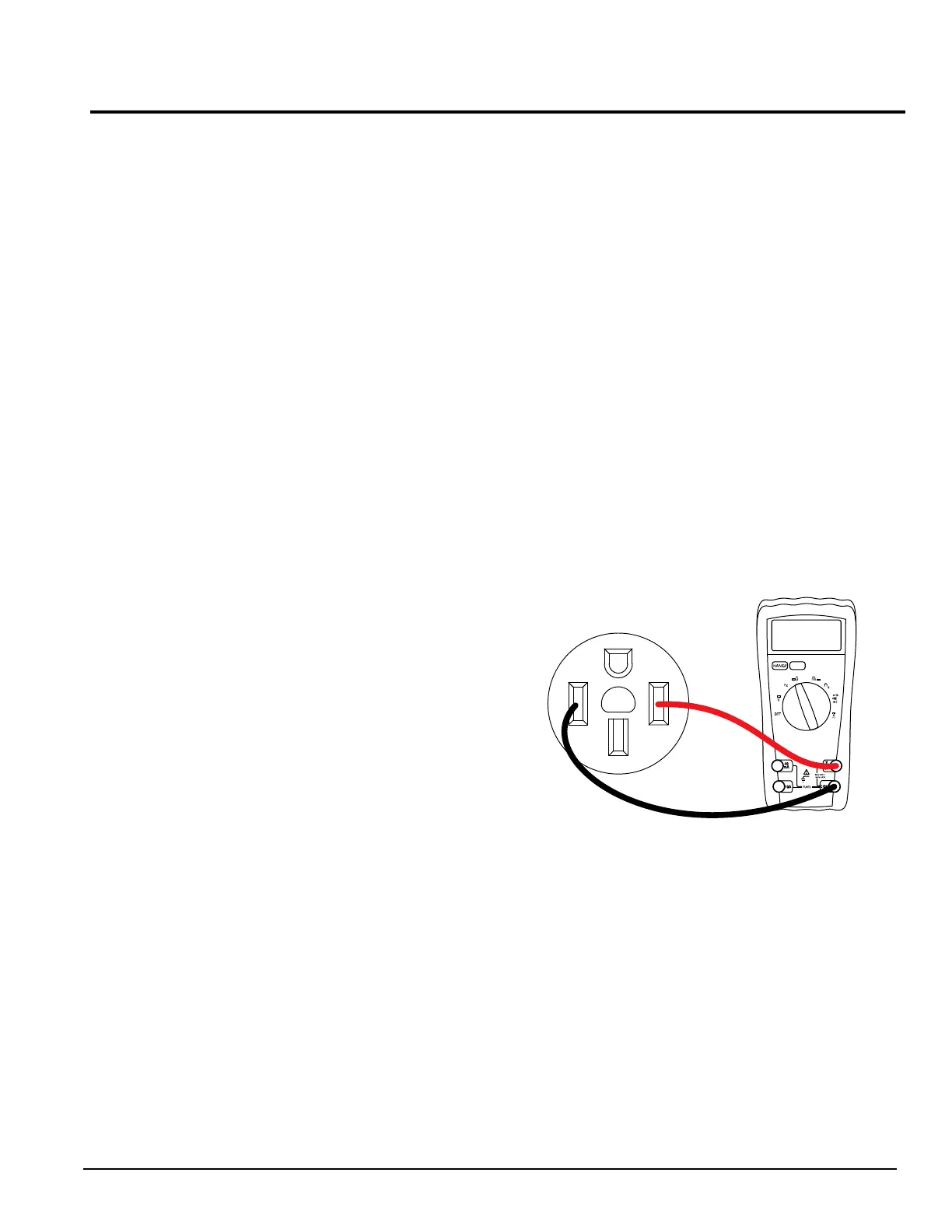
5. Set a digital multimeter (DMM) to measure AC
voltage.
6. See Figure 4-1. Place the meter test leads into the
50A outlet.
Figure 4-1. DMM Test Leads Connected to 50A Outlet
7. Read AC voltage.
8. Connect an AC frequency meter as described in
step 6.
9. Read AC frequency.
Results
For units rated 60 Hertz, no load voltage and frequency
should be approximately 238-242 VAC at 59-61 Hertz.
See Problem 1 – Voltage and Frequency Are Both
High or Lowin section 3.
240
50A

 Loading...


