Section 4 AC Diagnostic Tests
38 Diagnostic Repair Manual
Table 4-1. Test 4 Results – Fixed Excitation Test/Rotor Amp Draw Test (8-20 kW)
Test 5 – Check Stepper Motor Control
Procedure
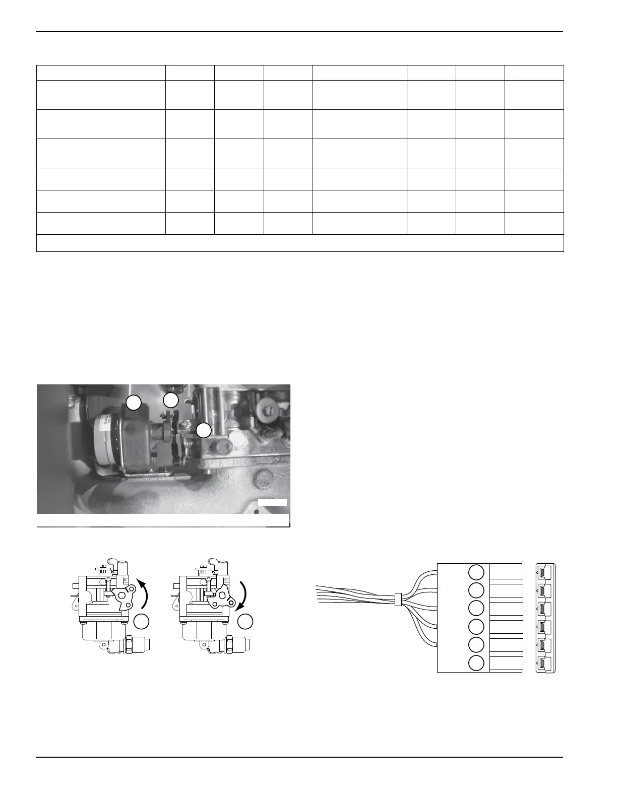
1. Remove air cleaner cover to access stepper motor.
2. Move throttle by hand and verify stepper motor,
linkage and throttle do not bind in any way. If any
binding is felt, repair or replace components as
needed. Some resistance should be felt as the
stepper motor is moved.
Figure 4-9. Stepper Motor, Linkage and Throttle
Figure 4-10. Throttle Positions
3. Move the throttle to the closed position by pushing
the throttle down as looking from above.
a. Set the idle control switch to OFF.
b. Set the start-run-stop switch (SW1) to START.
c. Watch for stepper motor movement. It should
move to the wide open position during
cranking. Once the unit starts the stepper
motor should move the throttle to a position to
maintain 60 Hertz.
4. If no movement is seen in step 3 remove the
control panel cover.
a. Verify the six pin connector on the printed
circuit board is seated properly. Remove the
connector and then replace it and test again.
b. See Figure 2-1. Verify the switches are set
correctly.
5. See Figure 4-11. If problem continues remove six
pin connector from printed circuit board.
6. Set DMM to measure resistance (ohms).
7. Carefully measure from the end of the six pin
harness as follows:
NOTE: Press down with the meter leads on the exposed
connector terminals. Do not probe into the connector.
Figure 4-11. Six Pin Connector Wire Colors
Results: A B C D E F G
Voltage Results Wire 2 & 6
Excitation Winding
Above 60
VAC
Above 60
VAC
Below 60
VAC
Zero or Residual Volts
Below 60
VAC
Below 60
VAC
Above 60 VAC
Voltage Results Wire 11S & 44S
Above 50
VAC
Below 50
VAC
Above 50
VAC
Zero or Residual Volts
Below 50
VAC
Below 50
VAC
Above 50 VAC
Voltage Results Wire 11S & 44S
Above 50
VAC
Below 50
VAC
Above 50
VAC
Zero or Residual Volts
Below 50
VAC
Below 50
VAC
Above 50 VAC
Rotor Amp Draw 12.5 kW 1.76-2.05 1.76-2.05 1.76-2.05 Zero Current Draw Above 2.5A 1.76-2.05
Zero Current
Draw
Rotor Amp Draw 15 kW 1.76-2.05 1.76-2.05 1.76-2.05 Zero Current Draw Above 2.5A 1.76-2.05
Zero Current
Draw
Rotor Amp Draw 17.5 kW 1.76-2.05 1.76-2.05 1.76-2.05 Zero Current Draw Above 2.5A 1.76-2.05
Zero Current
Draw
Match results with letter and refer to flow chart “Problem 2”
A. Stepper Motor B. Linkage C. Throttle
004657
A
B
C
004640
A B
A. Full Throttle
B. Closed Throttle
004641
A
A. Black
B. Brown
C. Yellow
D. Orange
E. Red
F. Emp t y
B
C
D
E
F

 Loading...


