Section 4 AC Diagnostic Tests
Diagnostic Repair Manual 37
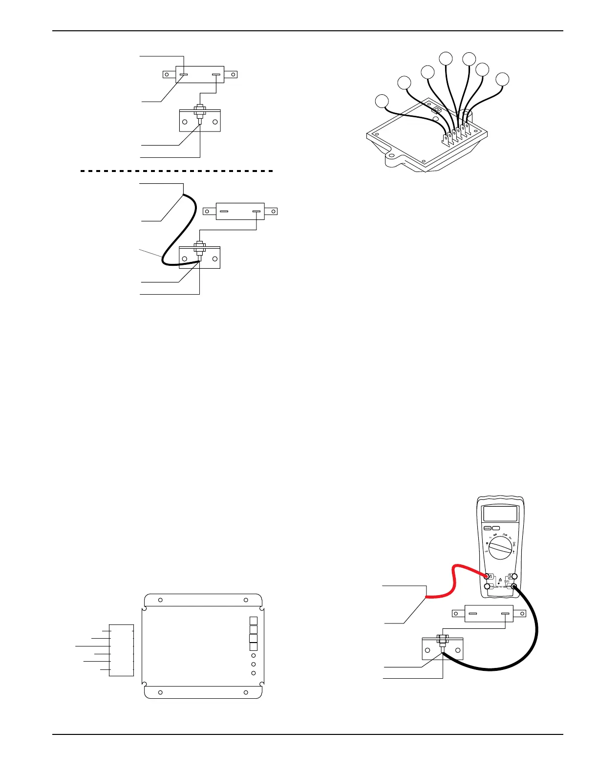
Figure 4-5. Fixed Excitation Test/Rotor Amp Draw Test
9. Set idle control switch to OFF.
10. Start the generator.
11. Measure and record the output voltage across wire
2 and wire 6.
AC voltage across wires 2 and 6 = _____________
12. Shut down the generator.
13. Connect wire 2 to the excitation circuit breaker.
14. See Figure 4-6 or Figure 4-7. Connect one meter
test lead to wire 11S.
15. Connect the other meter test lead to wire 44S or
22S, depending on older or newer style voltage
regulator.
16. Start the generator.
17. Measure and record the output voltage across
wires 11S and 44S, or 11S and 22S.
AC Voltage across wires 11S and 44S = __________
AC Voltage across wires 11S and 22S = __________
18. Set start-run-stop switch (SW1) to STOP.
Figure 4-6. Old Style Voltage Regulator Wire Number
Locations
Figure 4-7. New Style Voltage Regulator Wire
Number Locations
19. Shut down the generator.
20. Remove the jumper lead between wire 14 and
Diode D1.
21. Set the DMM to measure DC amperage (10 amp
range).
a. Switch the test leads on the meter if required.
22. See Figure 4-8. Connect the positive meter test
lead to wire 14.
23. Connect the negative test lead to wire 4 at diode
D1.
24. Start the generator.
25. Measure and record the DC rotor amp draw.
Rotor Amp Draw = _____________________
26. Shutdown the generator.
27. Connect the six pin connector, or wires to
terminals.
28. Connect wire 14 to the resistor R1.
Results
Refer to Table 4-1.
Figure 4-8. Measuring Amp Draw
2
$
$
7)2%
2%-/6%$
*5-0%2,%!$
2
0).
0).
0).
0).
0).
0).
3
3
D2
4
14
WIRE 14
REMOVED
14
4
R1
1.5 A

 Loading...


