Section 4 AC Diagnostic Tests
62 Diagnostic Repair Manual
7. Connect one meter test lead to wire 83 previously
removed from SW2.
8. See Figure 4-59. Connect the other meter test
lead to pin location J2-2 on the J2 connector.
a. Continuity should be measured.
b. If Continuity is not measured repair or replace
wire 83 between the J2 connector and terminal
block or between the terminal block and SW2.
Results
Repair or replace wiring as needed. Refer back to the
flow chart.
Test 54 – Check Idle Control
Transformers (ICT)
Procedure
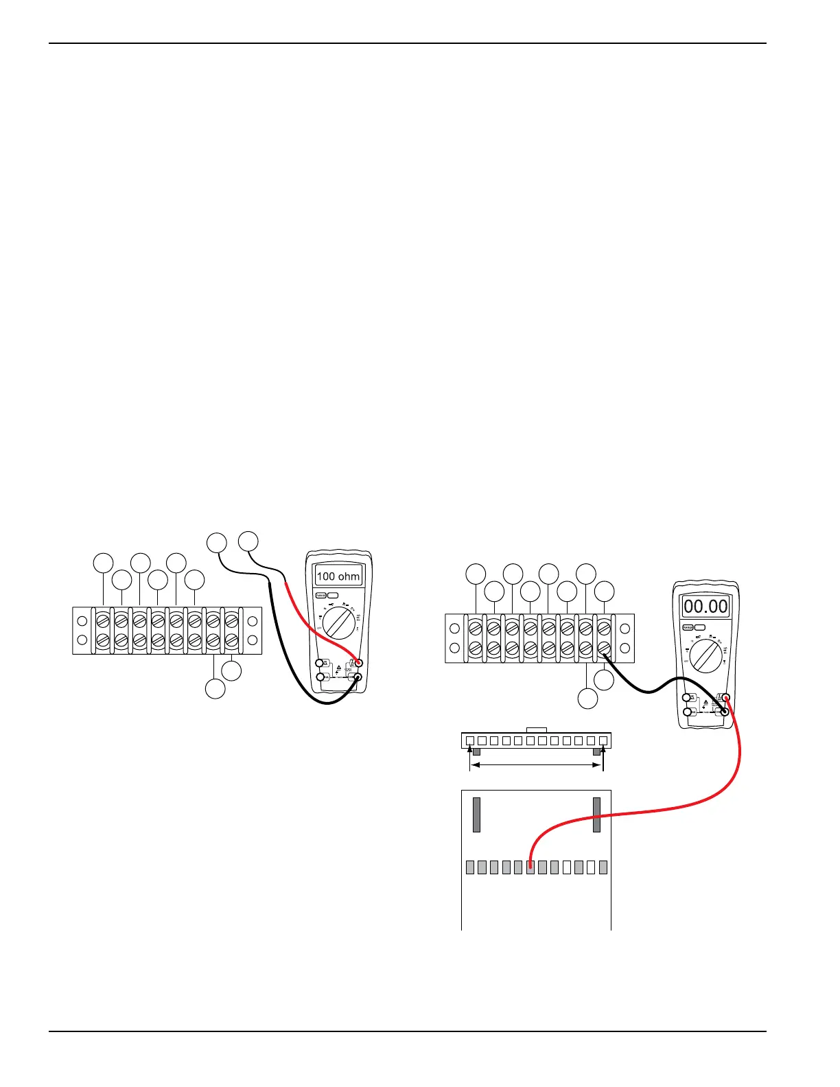
1. Set DMM to measure resistance.
2. See Figure 4-60. Remove the two idle control
transformer (ICT) wires from terminal block 1
(TB1).
NOTE: Where terminal block is not present, place meter
test lead on the wire at the termination point. If
necessary, use a small paper clip to probe beside the
wire so as not to damage the terminal in the connector.
Figure 4-60. Check Idle Transformer Wiring
3. Connect one meter test lead to one wire.
4. Connect the other meter test lead to the other wire.
a. Approximately 100 ohms should be measured.
b. If resistance is not measured repair or replace
the idle control transformers.
c. If resistance was measured proceed with step 5.
5. Set DMM to measure AC Voltage.
6. Connect one meter test lead to one wire.
7. Connect the other meter test lead to the other wire.
8. Turn the idle control switch (SW2) to OFF. The
generator should be running at about 60 HZ.
9. Apply a light load to the generator, such as an
electric drill.
10. When the drill is activated measure the voltage
output. The AC voltage should measure around 1-
2 VAC.
Results
Refer back to flow chart.
Test 55 – Check TR1 & TR2 Wiring
Procedure
1. Set DMM to measure resistance.
2. Disconnect the J2 connector from the printed
circuit board.
3. See Figure 4-61. Connect one meter test lead to
wire TR2 at terminal block 1 (TB1).
NOTE: Where terminal block is not present, place meter
test lead on the wire at the termination point. If
necessary, use a small paper clip to probe beside the
wire so as not to damage the terminal in the connector.
4. Connect the other meter test lead to pin location
J2-6 on the J2 connector previously removed.
a. Continuity should be measured.
5. See Figure 4-62. Connect one meter test lead to
wire TR1 at terminal block 1 (TB1).
6. Connect the other meter test lead to pin location
J2-3 on the J2 connector previously removed.
a. Continuity should be measured.
Figure 4-61. Check TR2 Wiring
Results
1. Repair or replace defective wiring.
2. If wiring tests good replace printed circuit board.
86 15B
167
BLK
0 229
83
BLK
TR2
TR1
TB1
J2 HARNESS CONNECTOR
86 15B
167
BLK
0 229
83
BLK
TR2
TR1
J2-1 J2-12

 Loading...


