Section 4 AC Diagnostic Tests
Diagnostic Repair Manual 47
Results
1. If continuity was measured the breaker is good
refer back to the flow chart.
2. If Infinity or a open condition was measured
replace the circuit breaker.
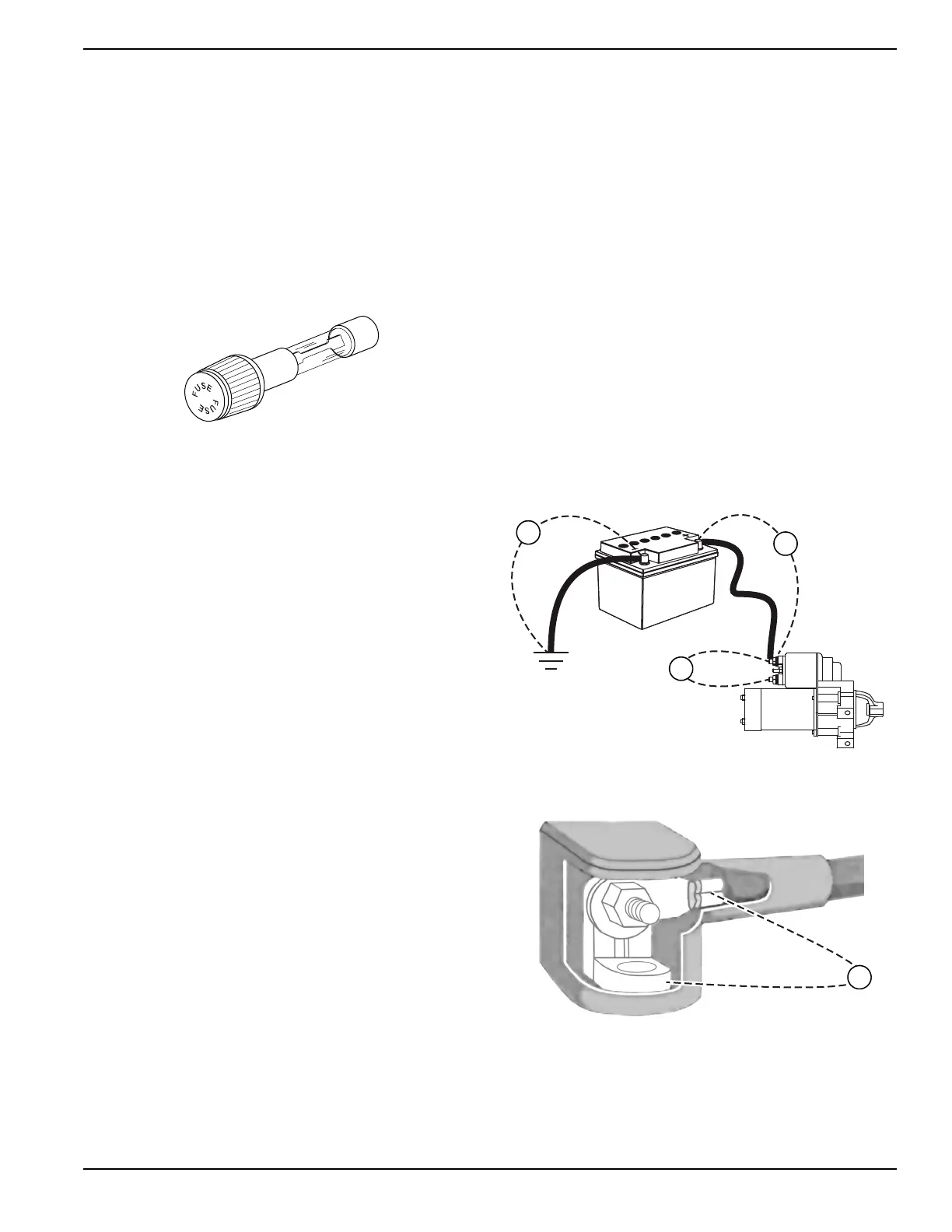
Test 21 – Check 10 Amp Fuse
Procedure
Push in on fuse holder cap and turn counterclockwise to
remove the cap with fuse. Inspect the fuse.
Figure 4-28. 10 Amp Fuse (Located in Rear of Control
Panel)
Results
If the fuse element has melted open, replace with an
identical size fuse. If fuse is good, refer back to flow chart.
Test 22 – Check Battery and Cables
General Theory
Battery power is used to (a) crank the engine and (b) to
power the circuit board. Low or no battery voltage can
result in failure of the engine to crank.
The battery charging circuit is not designed to recharge a
dead battery. As well, if there is a loose connection or
corrosion associated with a wire (positive or negative),
battery voltage may be present, but due to high
resistance, will not allow current to flow.
Electrical voltage drop varies according to current flow.
Voltage drop cannot be measured unless the circuit is
operated so current can flow through it. A crank attempt
will need to be performed to properly measure voltage
drop. This test will determine whether the battery, battery
cables, or both are at fault.
Procedure A – Perform Starter Circuit Voltage
Drop Test
1. Set a DMM to measure DC voltage.
2. Connect the red meter test lead to the positive
battery post and connect the black meter test lead
to the negative battery post.
a. If battery voltage is 12.1 VDC or below,
recharge the battery and retest.
b. If battery voltage is 12.2 VDC or above,
proceed to next step. (For this test, battery
voltage should be at least 12.2 VDC)
3. To inhibit any possible startup, turn off the fuel
source and ground wire 18 at the stud located
above the oil cooler. See Figure 4-39.
4. Refer to battery post and starter connections in
Figure 4-29 and Figure 4-30 then perform a
voltage drop test as indicated.
5. Set the start-run-stop switch to START. Allow the
engine to crank long enough to obtain a steady
measurement.
6. Record voltage readings from test points V1, V2,
V3 and V4. Although resistance-free connections,
wires and cables would be ideal, most of them will
contain at least some voltage drop. The maximum
voltage readings should be as follows:
a. 0.00-0.10 VDC across a connection or battery
post (V4).
b. 0.10-0.20 VDC on a ground connection.
c. 0.20-0.30 VDC across a wire or cable (V1, V2).
d. 0.20-0.30 VDC across a switch or starter
contactor (V3).
e. 0.40-0.50 VDC across the entire circuit
Figure 4-29.
Figure 4-30.
7. If voltage drop is greater than the above, based on
the circuit or component, clean or replace the failed
connection or component. If voltage drop test
results are within the above, based on the circuit or
component, refer back to the flowchart.

 Loading...


