EasyManuals Logo
Home>Generac Power Systems>Portable Generator>GP Series

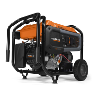
Generac Power Systems GP Series Diagnostic And Repair Manual

Generac Power Systems GP Series
98 pages
To Next Page IconTo Next Page
To Previous Page IconTo Previous Page
Page #84 background imageLoading...
Page #84 background image
Section 6 Electrical Data
80 Diagnostic Repair Manual
Wiring Diagram 12.5 & 15 kW (Units With Hourmeter) – Drawing No. 0D4609-D
GOVERNOR
ACTUATOR
+
-
WHITE
Y
X
G
30A TWISTLOK
120/240V
120V/20A
HOT HOT
3
1
WHITEWHITE
5
LINE
4
LOAD
2
C.B.
30A
C.B.
30A
C.B.
20A
C.B.
20A
C.B.
30A
30A
C.B.
0
LOP
FSS
SP2
IM2
D
IM1
SP1
D
IC
SSR
ENGINE WIRING
15
15
15
0
0
0
0
0
0
18
15
13
13
167
22
22
11
11
11
11
11
11
44
44
44
44
44
44
44
0
11A
11A
44B
11B
11C
11D
44D
22
22
22
0
0
0
0
0
0
0
0
0
0
0
GFCI
DUPLEX
120V/20A
HOT
3
1
HOT
WHITE
4
5
WHITE
2
G
WHITE
G
WHITE
120V/30A
TWISTLOK
120V/30A
TWISTLOK
F1
0
0
0
15
15
0
0
13
15
14
14
17
1
0
0
50A
C.B.
55
55A
11
0
11
44
86
86
BLACK
BATTERY
12V
RED
SM
SC
13
16
16
15
15
14 14
0
0
SCR
18
1
2
4
5
6
7
8
9
10
11
3
12
PIN #
167
0
0
44C
0
22
22
22
222222
GND
(START)
0
15
17
RUN
STOP
22
22
22
22
0
22
22
0
0
0
0
0
0
1413
91012
5
12
6
4
8
30
85
87a
86
87

Table of Contents

Other manuals for Generac Power Systems GP Series

Questions and Answers:

Question and Answer IconNeed help?

Do you have a question about the Generac Power Systems GP Series and is the answer not in the manual?

Generac Power Systems GP Series Specifications

General IconGeneral
BrandGenerac Power Systems
ModelGP Series
CategoryPortable Generator
LanguageEnglish

Related product manuals