19
GB 05 06 03 04
Sprayer setup
HyHy
HyHy
Hy
drdr
drdr
dr
aulics - contraulics - contr
aulics - contraulics - contr
aulics - contr
ol bool bo
ol bool bo
ol bo
x (type Z only)x (type Z only)
x (type Z only)x (type Z only)
x (type Z only)
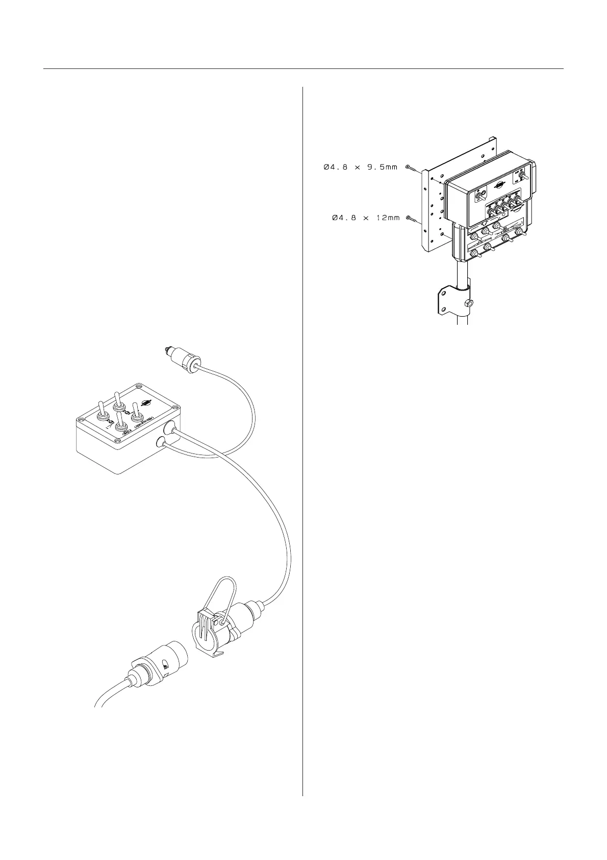
Installation of control box
1. Connect the plug A to the tractors 12V power system.
Try to hook-up the handle as close as possible to the
battery power supply. HARDI recommends using an
electric distribution box (ref. no. 817925) to ensure a
good power supply to various 12V attachments.
Note! Check with your dealer or tractor operators
manual for the best location to hook up the 12V system.
Note polarity: BROWN wire = Positive (+)
BLUE wire = Negative (-)
2. Route the cable, with the 7 pins, from the hydraulic
mount plate to the tractor.
3. Mount the hydraulic control box B in a suitable loca-
tion in the tractor cabin.
4. Connect the female 7 pin plug C from the switch box
to the 7 pin male plug D from the sprayer.
ContrContr
ContrContr
Contr
ol bool bo
ol bool bo
ol bo
x - EVx - EV
x - EVx - EV
x - EV
C operC oper
C operC oper
C oper
aa
aa
a
ting unitting unit
ting unitting unit
ting unit
The control boxes for EVC-operating unit is fitted in the
tractor cabin at a convenient place. Tapping screws can
be used for mounting.
Power requirement is 12V DC.
Note Polarity: BROWN wire = Positive (+)
BLUE wire = Negative (-)
The wires must have a cross sectional area of at least
4.0 mm to ensure sufficient power supply. For the EVC-
operating unit the tractor circuit should have an 8 Amp
fuse.
Use the HARDI Electric distribution box
(Ref. no. 817925) if the tractor has a doubtful power
supply.
T165-0013
AA
AA
A
BB
BB
B
DD
DD
D
CC
CC
C
T045-0010
 Loading...