34
GB 08 04
Operation
Use ofUse of
Use ofUse of
Use of
MANIFOLD v MANIFOLD v
MANIFOLD v MANIFOLD v
MANIFOLD v
alvalv
alvalv
alv
e sye sy
e sye sy
e sy
stemstem
stemstem
stem
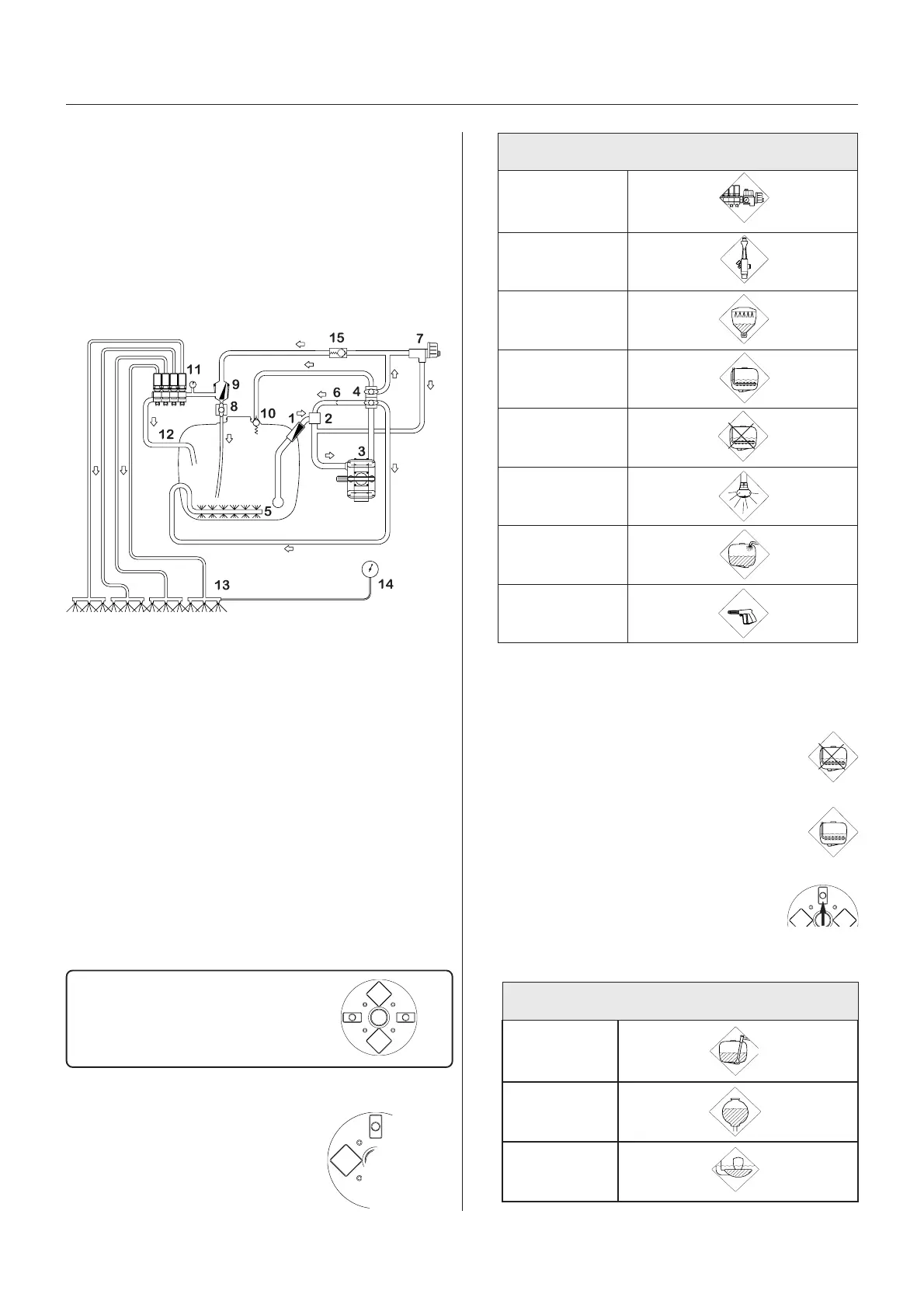
The following pictograms and colours are used for
visualizing the functions of the MANIFOLD valves:
Green disc = Pressure valve
Black disc = Suction valve
Yellow disc = Self-cleaning filter
A function is activated/opened
by turning the handle
towards the desired
function
OperOper
OperOper
Oper
aa
aa
a
ting the liquid syting the liquid sy
ting the liquid syting the liquid sy
ting the liquid sy
stemstem
stemstem
stem
MANIFOLD SYMANIFOLD SY
MANIFOLD SYMANIFOLD SY
MANIFOLD SY
STEMSTEM
STEMSTEM
STEM
The MANIFOLD SYSTEM is located at the left side of
the sprayer and permits operation of the liquid system
from one position. The modular MANIFOLD system
facilitates the addition of up to two optional extras on the
pressure side and one extra on the suction side.
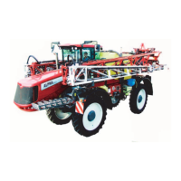
Function diagram - EVC (Standard)
1. Suction filter
2. Suction manifold (black)
3. Pump
4. Pressure manifold (green)
5. Agitation
6. Without agitation (pressure equalisation)
7. HARDI MATIC
8. Return line (Self-cleaning filter)
9. Self-Cleaning Filter
10.Safety valve
11.Distribution valves
12.Return from Pressure Equalisation
13.Sprayer boom
14.Pressure gauge
025
*Agitation
Normally, Agitation should be on but please refer to the
following rules of thumb:
1. Choose Without Agitation if a high level of
effervescence occurs in order to reduce the
amount of foam.
2. Choose Agitation when using powder
chemicals in order to avoid sedimentation.
3. Close the valve if spraying with a high
volume and it is impossible to achieve
sufficient pressure.
026
)erusserp(csidneerG-smargotciP
gninaelc-fleS
/retlif
tinugnitarepO
gnilliftsaF
ecived
RELLIFIDRAH
noitatigA
tuohtiW
noitatiga
gnihsulfknaT
elzzon
knatniamoT
nugyarpS
*
)noitcus(csidkcalB-smargotciP
morfnoitcuS
knatniam
knatgnisniR
gnilliF
ecived
Function
open
Closed
 Loading...