45
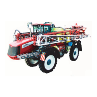
Adjustable Agitation Valve
DescriptionDescription
DescriptionDescription
Description
This new Adjustable Agitation Valve replaces the
existing agitation valve at your Hardi Manifold System.
It gives you the possibility to continiously adjust the
quantity of liquid that is used for agitation or by-pass.
FunctionFunction
FunctionFunction
Function
The Adjustable Agitation Valve replaces the existing
agitation valve, and should be located at the same place
in the Hardi Manifold System
Diagram shows where the replacement takes place.
The green pressure valve has 4 positions. Two positions
are for Agitation and Without Agitation (by-pass). The
other two are marked 0 indicating the valve is closed.
With the new Adjustable Agitation Valve it is possible
to combine these positions continously. For example if
you want to spray with a high volume rate at high(-er)
pressure and want agitation in same time. This situation
could be impossible with the standard valve.
DiaDia
DiaDia
Dia
gg
gg
g
rr
rr
r
am - Conam - Con
am - Conam - Con
am - Con
vv
vv
v
entional liquid syentional liquid sy
entional liquid syentional liquid sy
entional liquid sy
stemstem
stemstem
stem
(Section - see complete diagram in your instruction book).
T051-0011
AssembAssemb
AssembAssemb
Assemb
lyly
lyly
ly
LubricaLubrica
LubricaLubrica
Lubrica
te all O-rings befte all O-rings bef
te all O-rings befte all O-rings bef
te all O-rings bef
oror
oror
or
e assembe assemb
e assembe assemb
e assemb
lyly
lyly
ly
..
..
.
1. Remove cover behind MANIFOLD SYSTEM (platform
side).
2. Release cramps and remove hoses from the sides of
the existing valve.
3. Remove the existing valve by releasing the cramp
from the T-piece and unscrew the valve from the
bracket.
4. Fit the new agitation valve in the bracket and tighten
the union nut.
5. Mount cramp to T-piece.
6. Mount the hoses in the sides of the new Adjustable
Agitation Valve.
7. Put the cover back.
OperOper
OperOper
Oper
aa
aa
a
tingting
tingting
ting
MANIFOLD SYMANIFOLD SY
MANIFOLD SYMANIFOLD SY
MANIFOLD SY
STEMSTEM
STEMSTEM
STEM
See instruction book for information about selecting
optional equipment
AdjustaAdjusta
AdjustaAdjusta
Adjusta
bb
bb
b
le Agitale Agita
le Agitale Agita
le Agita
tion Vtion V
tion Vtion V
tion V
alvalv
alvalv
alv
ee
ee
e
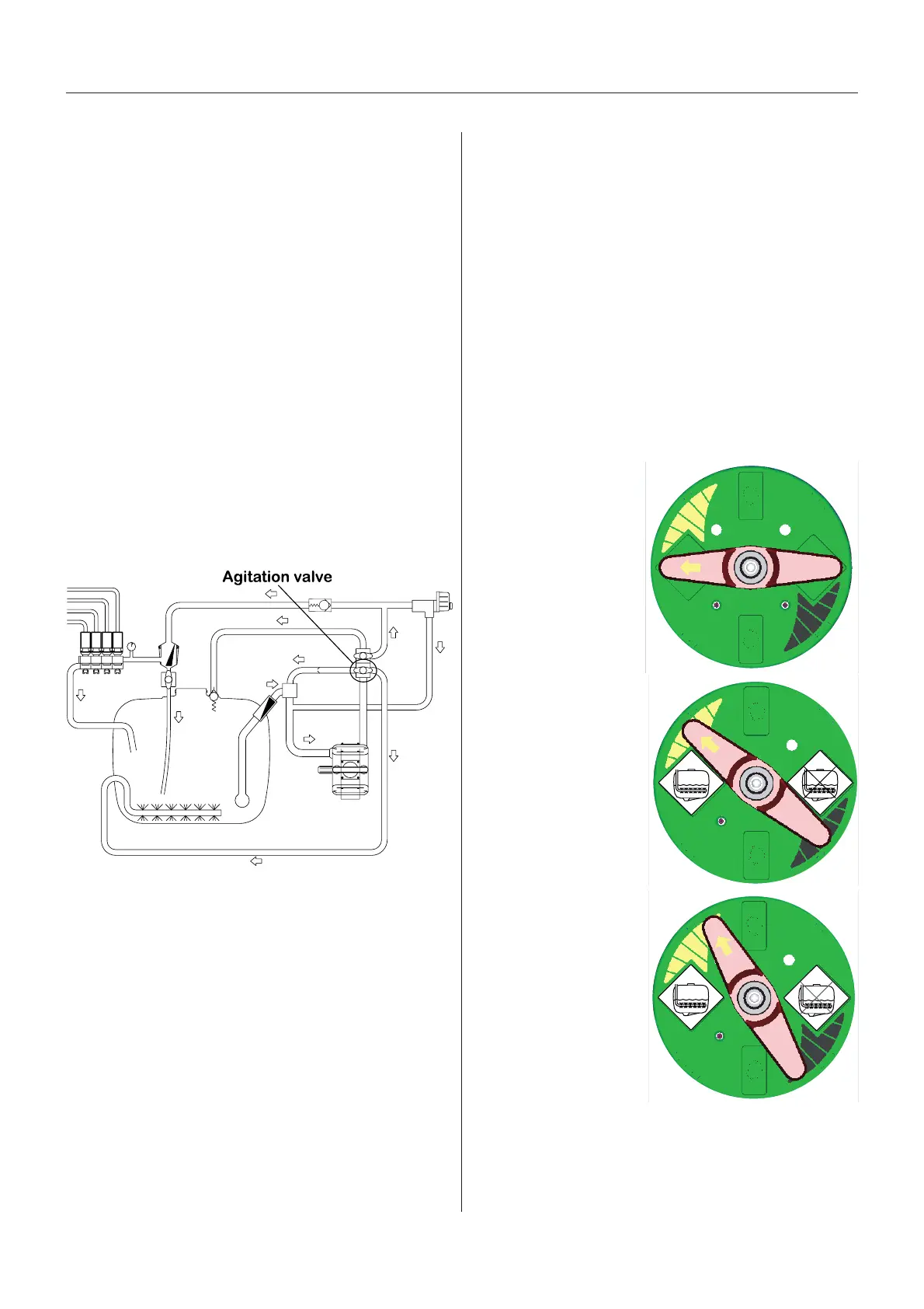
The valve is marked with arrows on the green disc that
indicates the amount of liquid that passes through the
valve. If handle is turned to a position near the tip of the
arrow, then only a small amount of liquid is allowed to
pass the valve. Otherwise, if handle is turned to a
position in the wide end of the arrow, it means that a
larger amount is passing the valve.
Now you have the posibility to continously adjust how
large amount of fluid from the pump is used for agitation
in the tank and for spraying.
Examples on handle positions at different agitation
quantities:
By-passBy-pass
By-passBy-pass
By-pass
When using agitation and you want to turn it off, then
turn the handle 180 degree around. This means that
agitation is off but the spraying pressure remains the
same - opposite to closing the valve, which will increase
the pressure.
T020-0047
T020-0046
T020-0048
1. Handle is in same
position as (open)
agitation position at
the original valve.
Agitation quantity is
100%.
2. Handle is positioned
at the middle of the
arrow (in agitation
side of the disk).
Agitation quantity is
50%.
3. Handle is positioned
near the tip of the arrow
(in agitation side of the
disk). Agitation quantity
is 10%.
GB 08 06
 Loading...