Ill. ENGINE
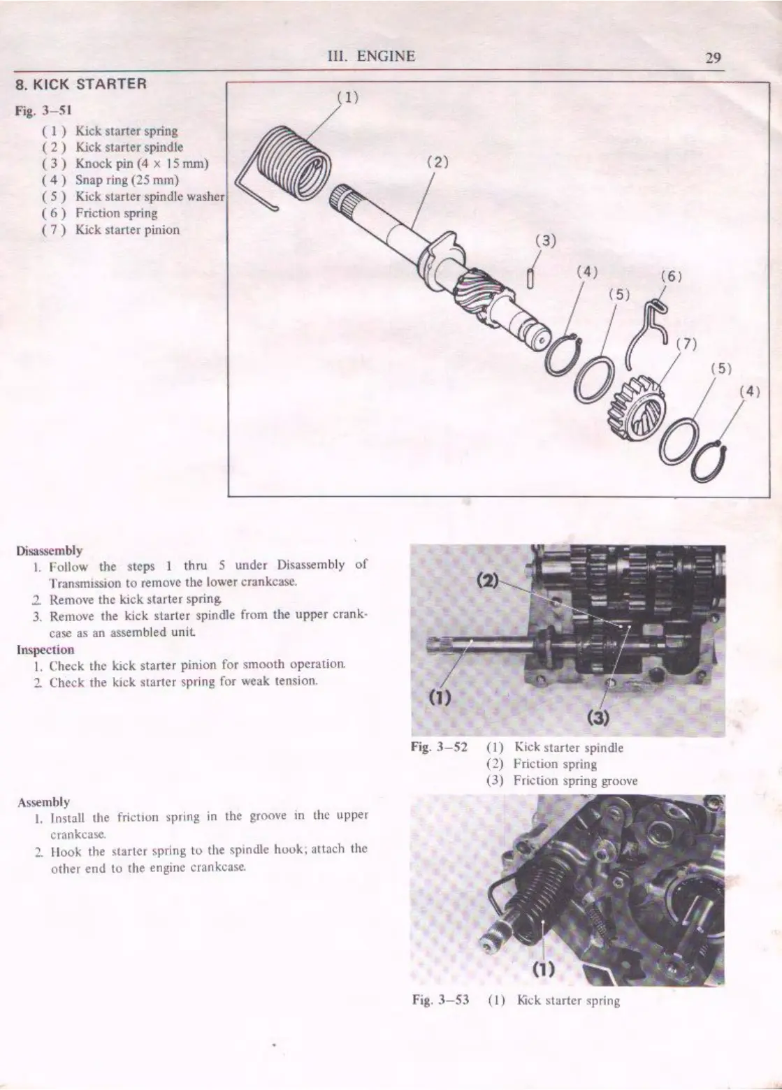
8. KICK STARTER
Fig.
3-5
1
( 1 )
Kick starter spring
(
2)
Kick starter spindle
(
3)
Knock pin
(4
x 15 mm)
(
4)
Snap ring (25 mm)
( 5 ) Kick starter spindle washer
(
6)
Friction spring
( 7 ) Kick start
er
pinion
Di
sassembly
(
I)
I.
Follow the steps J thru 5 under Disassembly
of
Transmission
to
remove
the
lower
crankcase.
2 Remove the kick starter spring
3. Remove the kick starter spindle from
tl1e
upper crank•
case
as
an
assembled
unil
ln.spection
I.
Check the kick starter pinion for smooth operation
2 Check the kick starter spring for weak tension.
Asse
mbl
y
I.
lnstaU
the friction
sp1
i
ng
in
the
groove
in
the
upper
Cl'ankcasc.
2 Hook the starter spring
lo
the spmdle hook; attach the
other
en<l
to
{he
engine
crankcase.
(2)
(3)
Fig.
3-52
(I)
Kick starter spindle
(2)
Priction spring
(3)
Friction spring groove
Fig.
3-53
(I)
l<ick
starter spring
29

 Loading...