EasyManuals Logo

Honda CB200 User Manual

Honda CB200
98 pages
To Next Page IconTo Next Page
To Previous Page IconTo Previous Page
Page #37 background imageLoading...
Page #37 background image
111.
ENGINE
11. CRANKCASE
Fig.
3-64
( J )
Upper
crankcase
( 2 )
Lower
crankcase
(
3)
Dowel pin A
(10
x
14mm)
( 4 ) Oil
separate,
( 5 ) Oil separator
set
bar
(
6)
Cable
clip
R
( 7 ) Cable clip A
(
8)
O-ring (33.5 X
3mm)
( 9 ) Drain
plug
1 Disassembly
1.
Remove
the
cylinder
head,
cylinder
and
piston.
See
page
14.
2 Separate
the
upper
and
lower
crankcases
and
remove the
c,ankshaft, mainshaft. countershaft)
gear
shift
drum
and
kick starter.
3.
Remove
the
oil
se
parator
and
take
out
the
set
bars.
Remove
the
separator
from
the
low
er
crankcase.
Inspection
1.
Check
the
crankcase oil passage for dogging.
Assembly
1.
Apply a
unifonn
coat
ing
of
proper
sealing
agent
to
the
crankcase
mating
surfaces.
2.
Make sure all dowel pins
arc
properly
installed in their
respective
po
s
itions.
3. Tighten nine
6mm
holls
and
nine
8mm
bolts.starting
at
the
ce
nter
toward
outside
in
criss-cross fashion.
Use
care
not to
damage
the
starting motor ca
bl
e while
tightening.
Use
each
bolt
in
its proper positio
n.
Torque
specifications:
6mm
holt
70-110
kg-<:m
(5.1 -
8.0
lbs-ft)
8mm
bolt 200 260
kg-<:m
(14.5-18.8
lbs
-f
t)
Fig.
3-65
(I)
Oil
separator
(2)
Separator
set
bar
(1
>-------
F
.
,~
)
,g .
.l-()6
( I) (,mm
bolt
(2)
8mm
bolt
(J)
Starting
motor
ca
hl
e
33

Questions and Answers:

Question and Answer IconNeed help?

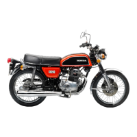
Do you have a question about the Honda CB200 and is the answer not in the manual?

Honda CB200 Specifications

General IconGeneral
Compression Ratio9.0:1
Fuel SystemCarburetor
Transmission5-speed
Front SuspensionTelescopic fork
Rear BrakeDrum
Fuel Capacity12 Liters
Rear SuspensionTwin shock absorbers

Related product manuals