-
2
-
--
---11.
INSPECTION
AND
ADJUSTMENT--------'
'fhis
section describes
the
inspection and
adjustment
procedures
for
the
impo
rtalll ilcrns
of
the periodical maintenance
of
the IIONOA
200
Mo<lcl
CIJ
·CL200.
Cross-refer
to
PfRlOOICAL
MAINTENANCE SCHEDULE on page
76.
For
the
items
other
than
those
not
descrihed in this section.
refer
to
the
"Inspection"
of
each
part
in
this manual.
1.
TAPPET
Inspection
a,1d
adjustment
of
the
tappet
clearunce
should
be
made while
the
engine is cold.
I.
Open
the
seat
and
remove the fuel tank.
2 Remove lhc
intake
and
exhaust
tappet
adjusting hole
caps
3.
Remove
the generator cover.
4. While slowly rotating
the
generator
rotor
counterclock
-
wise
wat.;:h
t11e
intake
,•ah,•e
tappet.
When this
tappet
goes dO\\'l all llte way and
then
starts
10 lift, you
must
then
watch
for
the alignment
of
the
index
mark
and
"T'
mark
In
this position, the piston
will
be
at
T. O.C.
(top
dead
center)
of
the
compression
stroke
and
the
intake
and
exhaust
valves
should
be fully
closed.
5.
Check
the
clearance
of
both
valves by inscrtu1g the feeler
gauge between
the
valve
stem
and
the
tappet
adjusting
screw.
If
the clearance is
correct
there
Will
be
slight
drag
or
resistance as the gauge is
inserted
To
adjust,
loosen the
lock
nut
and turn the adjusting
screw
as
required.
Tappet
Intake
valve:
0.05mm
{o.002
in
.
Clearance Exhaust valve:
0.05mm
(0.002
in.)
•
NOTE:
,
After
tightening
the
lock
nut,
check
the
clcar
.
ance
and,
if
necessar)'? re.adjust.
6.
Rotate
the
generator
rotor
one full turn
until
the
marks
aljgn. Apply the same
techniq1.1c
as above
to
the
remain•
ing
valves.
~
,
I
(
2.
BREAKER POINT GAP ANO
IGNITION
TIMING
Breaker
point
gap
t Remove the
generator
and
point
covers.
1 Using a
17mm
wrench,
turn
the
generator·
rotor
counter
•
clockwise
and
check
t~~
point
gap
when
it
is at
its
maximum.
Specified
maximum
gap:
0.3-0.4mm
(0.012-0.016-in.)
'fo
adjust
the
gap, loosen
the
locking screws
and
move
the
breaker
point
plate.
After
adjustment,
tighten the
locking screws and recheck the gap.
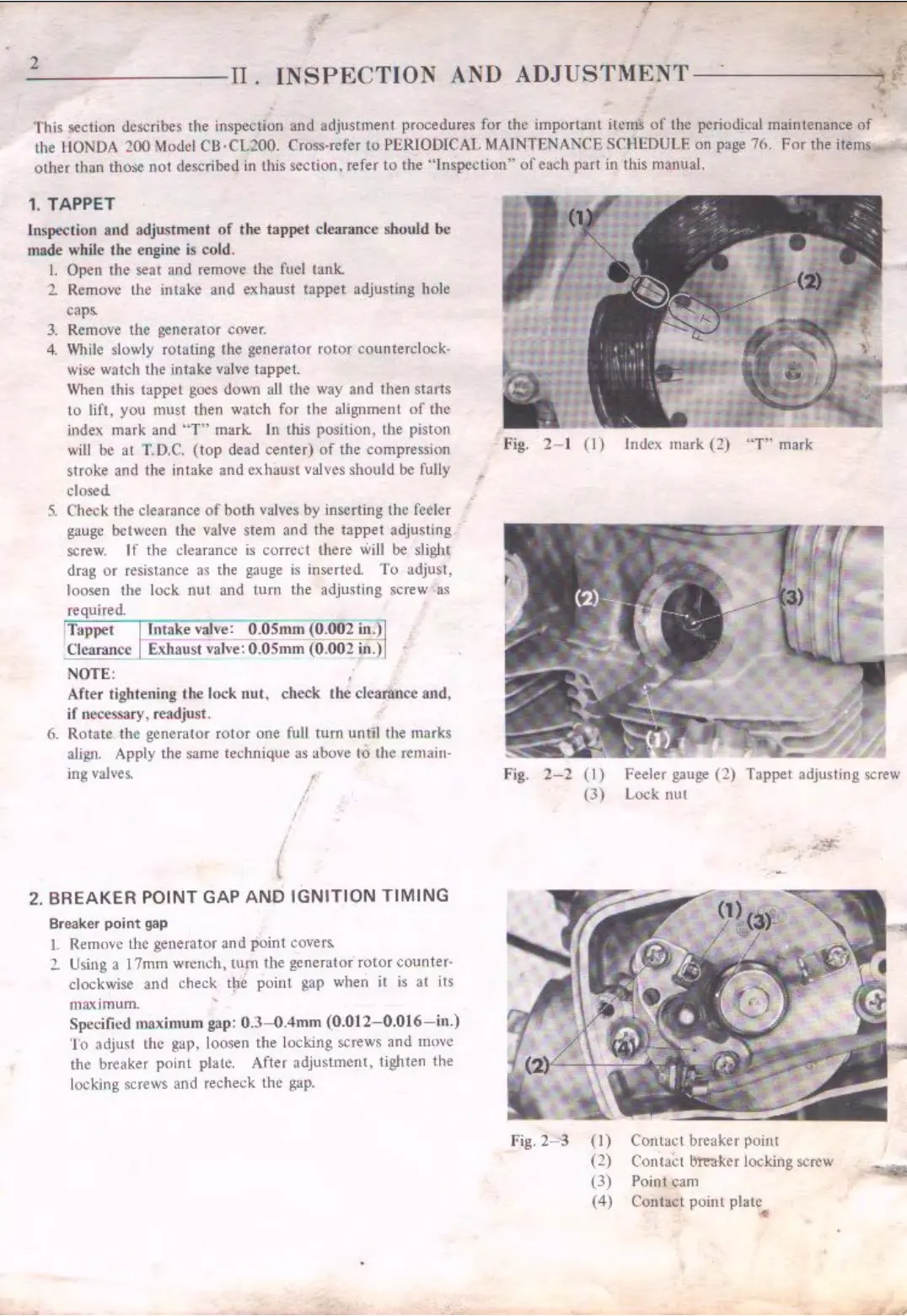
fig.
2- 1
(1)
Index
,nark
(2)
"T"
mark
f'ig.
2-2
(I)
(3)
f'ig. 2-
-3
(I)
(2)
(3)
(4)
Feeler gauge
(2)
Tappet
adjusting screw
Lock
nut
Contact
breake,· point
Contact
bnra-kcr locking screw
Poiot
cam
Contac
t
poilll
plate
•

 Loading...