9-7
HRN216 IGNITION COIL/FLYWHEEL
Remove the feeler gauge, and then recheck the air gap.
Install the fan cover (P. 7 -3
).
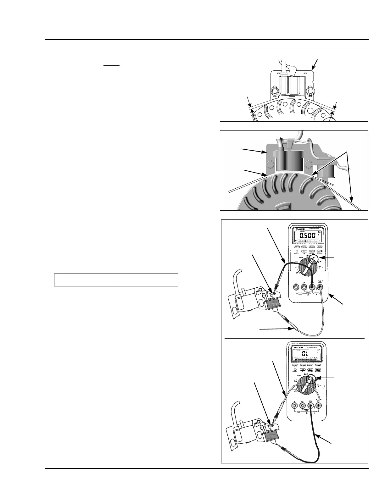
CHARGE COIL AND DIODE TEST
1. Select the diode function of a digital multimeter.
2. Attach the red lead to the laminate core (ground) and the
black lead to the charge coil terminal.
3. Check for the specified voltage drop.
4. Reverse the test leads so that the black lead is on the
laminate core and the red lead is on the charge coil
terminal.
The meter should read OL (Over Limit) or
OC (Open Circuit).
Follow the meter manufacturer’s instructions for testing
diodes. Some meters show current flow from negative (-)
to positive (+), while others show current flow from
positive (+) to negative (-). The polarity of the meter does
not matter when testing diodes. As long as the meter
shows current flow one way and not the other, the diode
is good.
5. Replace the ignition/charge coil if any of the above tests
are out of specification.
Specified voltage 0.4 ~ 0.8 VDC
0.30 ~ 0.50 mm
(0.012 ~ 0.020 in)
0.30 ~ 0.50 mm
(0.012 ~ 0.020 in)
IGNITION COIL
PKA/VKA/VYA TYPES
0.30 ~ 0.50 mm
(0.012 ~ 0.020 in)
0.30 ~ 0.50 mm
(0.012 ~ 0.020 in)
IGNITION
COIL
VLA TYPE
DIODE
TEST
FUNCTION
RED TEST
LEAD
BLACK TEST LEAD
CHARGE COIL
TERMINAL
DIGITAL
MULTIMETER,
FLU-88
RED TEST LEAD
BLACK
TEST
LEAD
DIODE
TEST
FUNCTION
CHARGE COIL
TERMINAL

 Loading...