2-14
SERVICE INFORMATION HRN216
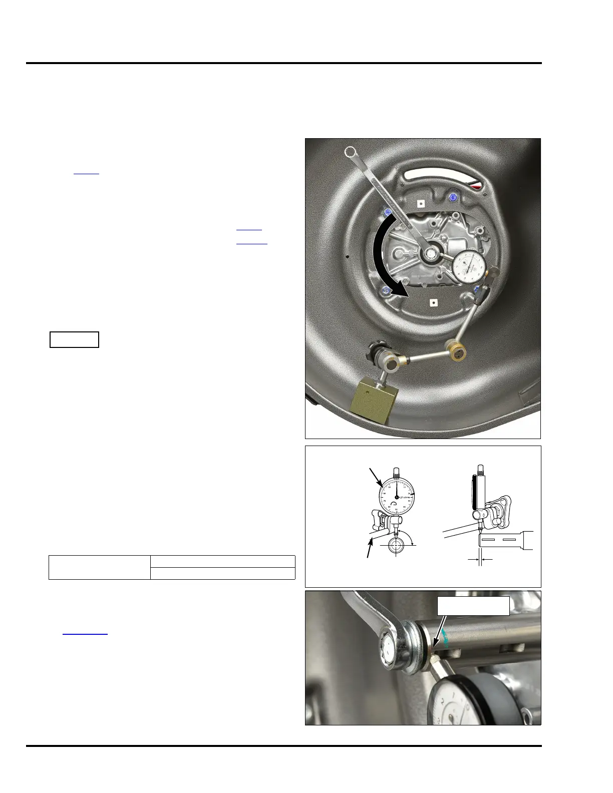
CRANKSHAFT RUNOUT INSPECTION
If the mower has excessive vibration, or if blade replacement is required because of damage caused by an object
hitting the blade, inspect the crankshaft runout.
INSPECTION
1. Disconnect the spark plug cap, and remove the spark
plug (P. 3 - 8
).
2. Turn the fuel valve to the OFF position, and then tilt the
mower on its side so the carburetor is up.
3. Remove the blades and blade holder (PKA, VKA, VLA
types) or Roto-Stop assembly (VYA type) (P. 4 -1
).
4. Remove the Roto-Stop cover and shutter (P. 12-1
).
5. Attach a dial indicator magnetic base to the lower
portion of the metal mower deck surface.
6. Position the tip of the dial indicator perpendicular to the
crankshaft (90 degrees in both directions) between the
very end of the crankshaft and the first small keyway
as shown.
When checking the crankshaft runout, do not allow the
dial indicator tip to drop into any of the keyways or the
dial indicator tip can be damaged.
7. Zero the dial indicator.
8. PKA/VKA/VLA types:
Hold the flywheel brake lever against the handlebar
using a strap.
9. Install the blade holder bolt into the end of the
crankshaft until it bottoms out.
10. Use a 14 mm wrench to turn the blade holder bolt
counterclockwise and measure the crankshaft runout.
IMPORTANT: You can only rotate the crankshaft
approximately 330 degrees before the dial indicator tip
will fall into the large keyway. Pay attention to where the
dial indicator tip is at all times.
11. If the runout exceeds the service limit, replace the
crankshaft. See “Damaged Crankshaft Replacement”
on page 10-9
.
Crankshaft Runout
Service Limit
0.20 mm (0.008 in)
90°
1 ~ 3 mm
(0.04 ~ 0.12 in)
DIAL INDICATOR, FFL-72-520-300
(commercially available)
MAGNETIC BASE,
FFL-72-585-010
(commercially available)
Place the dial
indicator tip here.

 Loading...