5-7
HRN216 ENGINE REMOVAL/INSTALLATION
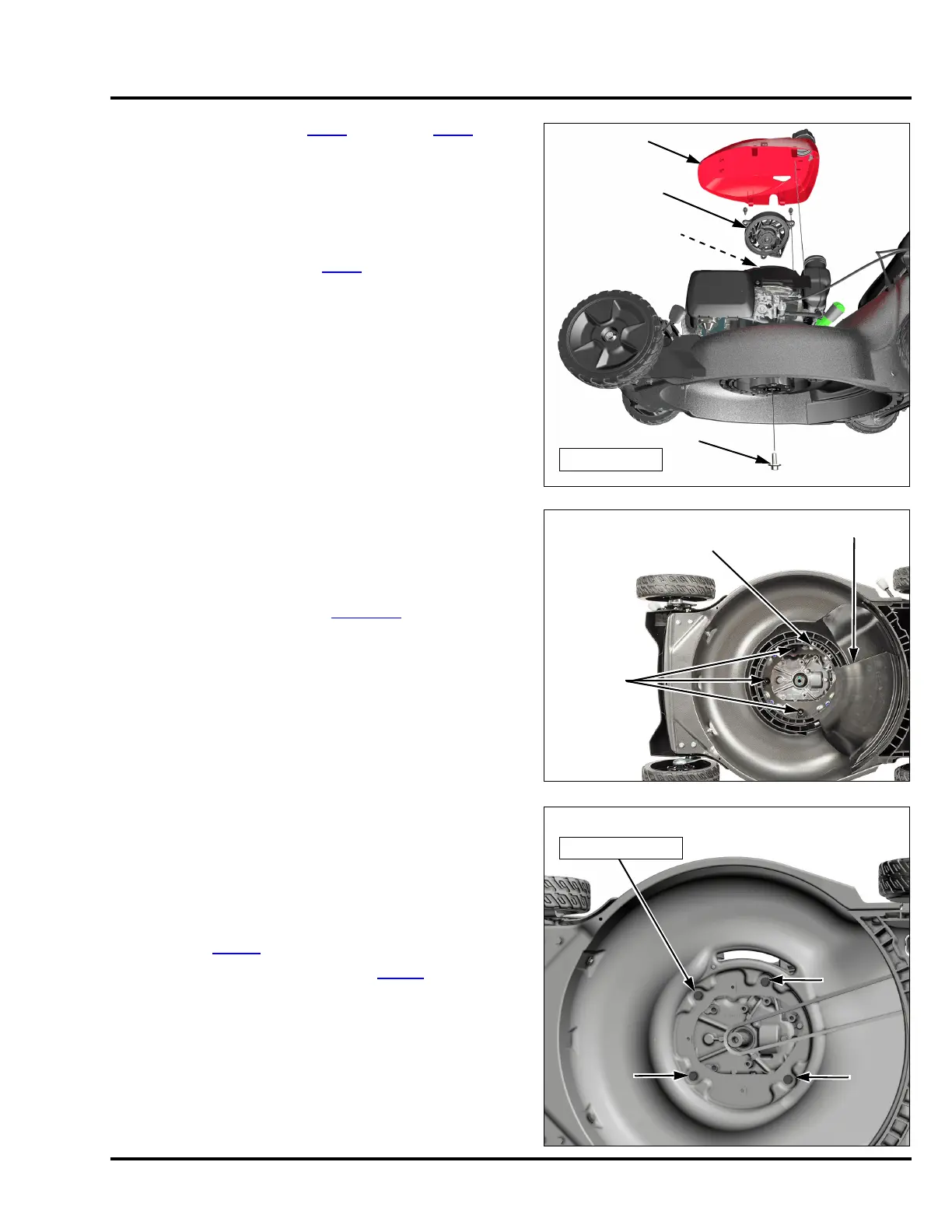
7. Remove the top cover (P. 7 -1 ) and recoil (P. 7 - 2 ). Hold
the flywheel nut with a 19 mm socket while removing the
center Roto-Stop special blade holder bolt.
8. Pull the Roto-Stop brake assembly off the crankshaft as
a complete assembly.
9. Remove the drive pulley (P. 4 - 6
).
10. Remove the two shoulder bolts attaching the Clip
Director® lever.
11. Remove the three screws and Roto-Stop cover/shutter
from the mower deck. See page 12-1
for detailed
removal instructions.
12. Support the engine, and remove the four 5/16-24 x 1
inch engine mounting bolts.
13. Remove the engine.
INSTALLATION
Installation is done in the reverse order of removal.
• Be sure the belt is properly routed through the shutter
assembly (P. 1 2- 4
).
• Reinstall the Roto-Stop assembly (P. 4 -11
).
Tighten the engine mounting bolts to the specified torque.
TORQUE: 21.6 N•m (15.9 ft-lb)
TOP COVER
RECOIL
FLYWHEEL NUT
BLADE HOLDER BOLT
54 N•m (40 ft-lb)
SCREW (3)
ROTO-STOP COVER/SHUTTER
SHOULDER BOLT (2)
5/16-24 x 1 in BOLT (4)
21.6 N•m (15.9 ft-lb)

 Loading...