11-21
HRN216 HANDLEBAR/ CABLES/CONTROLS
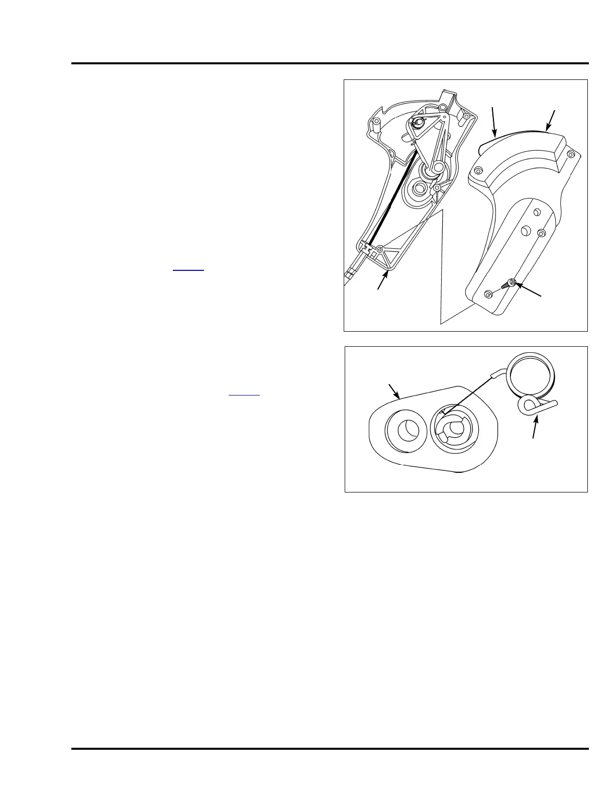
5. While holding the push knob in the Roto-Stop right case,
carefully install the right case on the left case.
• Confirm that the case halves seat together and install
the four self-tapping screws.
• Verify that the yellow push knob pushes in and
releases properly.
6. Install the Roto-Stop control on the handlebar.
7. Route the Roto-Stop cable down through the cutter
housing and to the ball plate.
8. Install the Roto-Stop cable ball end in the ball plate.
Secure the Roto-Stop cable locking tabs in the return
spring hook.
9. Install new cable ties securing the Roto-Stop cable to the
Smart Drive cable (P. 2 - 2 4
).
10. Install the rear scroll.
11. Install the blade control lever spring on the
Roto-Stop control assembly as shown and install the
blade control lever.
12. Readjust the Roto-Stop cable (P. 3-13
).
13. Start the engine and confirm proper Roto-Stop
operation.
ROTO-STOP
RIGHT CASE
SELF-TAPPING
SCREW (4)
ROTO-STOP
LEFT CASE
PUSH
KNOB
BLADE CONTROL
LEVER SPRING
ROTO-STOP
CONTROL
ASSEMBLY

 Loading...