About these instructions
20
1. About these instructions
Fold out the left-hand cover. This shows all the operating
elements and connections. Leave the cover folded out while
reading further.
Legend for fold-out page
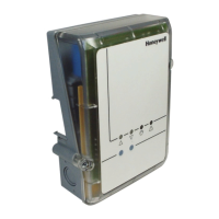
Fig. 1 Device overview
Fig. 2 Display and operating elements
(1)
LED 1 Mixing valve OPEN
(2)
LED 2 Mixing valve CLOSED
(3)
LED 3 PUMP
(4)
LED 4 Fault
(5) Mixing valve CLOSED button
(6) Mixing valve OPEN button
Fig. 3 Connections
(7) Connection of inlet sensor
(8)
Connection of power supply, pump, mixing valve
(230 V~)
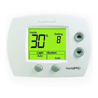
Fig. 4
Operating elements and display CM67RFMV
(for description refer to page 21)
Fig. 5 Opening/closing the housing
2. General safety instructions
DANGER
,
Danger to life through electric
shock!
Contacts that are open are live.
► Ensure that the device is de-
energised.
► Have all the work carried out by
authorised qualified personnel.
► Observe the valid IEE regulations
during the installation.
WARNING
Damage to the devices!
Short-circuiting through humidity and
moisture.
► Mount the devices at a site that is
protected against humidity and
moisture.
WARNING
Damage to the devices!
► Secure the connecting cable with the
cable gland (Eurofix).
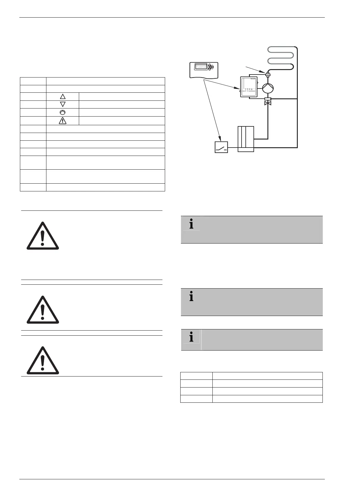
3. Overview
CM67RFMV
Boiler
HC60NG/
R6660D
Flow temperature
sensor
Pump
Parameter
settings
Universal Mixing
Valve Controller
HM 80
T7414C1012
3.1. Preconfigured set HMC 82
Scope of delivery (see fold-out page, Fig. 1)
• 1 Universal Mixing Valve Controller HM 80 (A)
• 1 Chronotherm CM67RFMV (B)
• 1 Flow temperature sensor T7414C1012 (C)
• 4 Eurofix cable glands, 4 nuts M16x1.5 (D)
The set HMC 82 is provided preconfigured.
The Universal Mixing Valve Controller HM 80 is
already assigned to the CM67RFMV at this set
(no teach-in required).
3.2. Preconfigured set HMC 80
Scope of delivery (see fold-out page, Fig. 1)
• 1 Universal Mixing Valve Controller HM 80 (A)
• 1 Chronotherm CM67RFMV (B)
• 4 Eurofix cable glands, 4 nuts M16x1.5 (D)
The set HMC 80 is provided preconfigured.
The Universal Mixing Valve Controller HM 80 is
already assigned to the CM67RFMV (no teach-in
required).
3.3. Individually provided devices
In the case of individually provided devices a
teach-in as described in the instructions always
has to be carried out.
Overview of the individually available devices (see fold-
out page Fig. 1):
Position Device
A Universal Mixing Valve Controller HM 80
B Chronotherm CM67RFMV
C Flow temperature sensor T7414C1012
 Loading...