Appendix
30
9. Appendix
9.1. Help with problems
Problem Cause/Solution
No commissioning
is possible
Incorrect connection
► Check the wiring.
LED 4 flashes
rapidly
(1/9 On/Off)
No device installed
► Carry out the teach-in.
LED 4 lights up
constantly and the
mixing valve is
closed
Inlet sensor is short-circuited or wire
break
► Check the sensor.
If a sensor that is no longer needed was
connected to the HM 80, the HM 80 has
to be reset to the state of delivery and
has to be assigned again to the
CM67RFMV.
Mixing valve
direction of
movement incorrect
Connection transposed
► Use the button OPEN/CLOSED to
check the direction of movement and
connect correctly, if applicable.
Control response
incorrect
► Check the set room temperature
setpoint at the CM67RFMV.
► Check the inlet sensor.
► Check the parameters set at the
CM67RFMV.
► Check the assignment.
► Check the radio transmission.
LED 4 flashes
(9/1 On/Off)
Radio connection faulty
► Check the radio transmission.
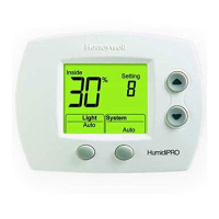
Chronotherm CM67RFMV
No display
► Check
– whether there are batteries in the
battery compartment.
– whether the paper strips between
the batteries have been removed.
– whether the batteries are inserted
in the correct direction.
► Replace the batteries, if necessary.
Display shows
flashing battery
symbol
► Remove the battery compartment
and insert it correctly.
► Replace the batteries, if necessary.
The symbol is
displayed
► Remove the battery compartment
and insert it correctly.
► If the symbol does not disappear
within a few minutes, call the installer.
9.2. Technical data
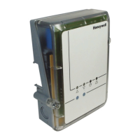
Universal Mixing Valve Controller HM 80
Input/Output voltage 230 V~, 50 Hz
Current consumption Max. 6 A
Ambient temperature 0 to 50 °C
Storage temperature –20 to +70 °C
Humidity 5 to 90 % relative humidity
Frequency (receiver) 868.3 MHz
Dimensions 121x161.5x46 mm (WxHxD)
Material Base: PA-GF 25-FR
Hood: PC -FR (VO certified)
Degree of protection IP54
Fire class V0
Pump relay
3 A, cos ϕ 0.7; no isolated output
Mixing valve relay
3 A, cos ϕ 0.7; no isolated output
Chronotherm CM67RFMV
Voltage supply 2x1.5 V LR6AA (alkaline) batteries
Dimensions 155x105x30 mm (WxHxD)
Frequency (transmitter) 868.3 MHz
Flow temperature sensor
NTC20 –30 to +110 °C
Sensitivity NTC 20 KΩ 20 KΩ 25 °C, non-linear
Precision NTC 20 KΩ ±1 °C
Cable length 1 m (max. 100 m)
9.3. Device and function definition in
accordance with EN 60730-1
• Purpose of the device is temperature controlling
• Device fulfils Protection class 1, EN 60730-1,
EN 60730-2-9
• Independently installable electronic control system with
fixed installation
• Type of action is Type 1.B
• Temperature for ball-thrust hardness test for housing
components 75 °C and for live parts such as, for
example, terminals 125 °C
• EMC emitted interference test at 230 V~, 50 Hz, 1400 VA
maximum
• Pollution severity is 2
• Rated voltage is 4000 V (corresponding to Overvoltage
category III)
• Software class is A
• Cooling optional
9.4. WEEE directive 2002/96/EC –
Waste Electrical and Electronic
Equipment directive
► At the end of the product life dispose of
the packaging and product in a
corresponding recycling centre.
► Do not dispose of the unit with the usual
domestic refuse.
► Do not burn the product.
 Loading...