Appendix
31
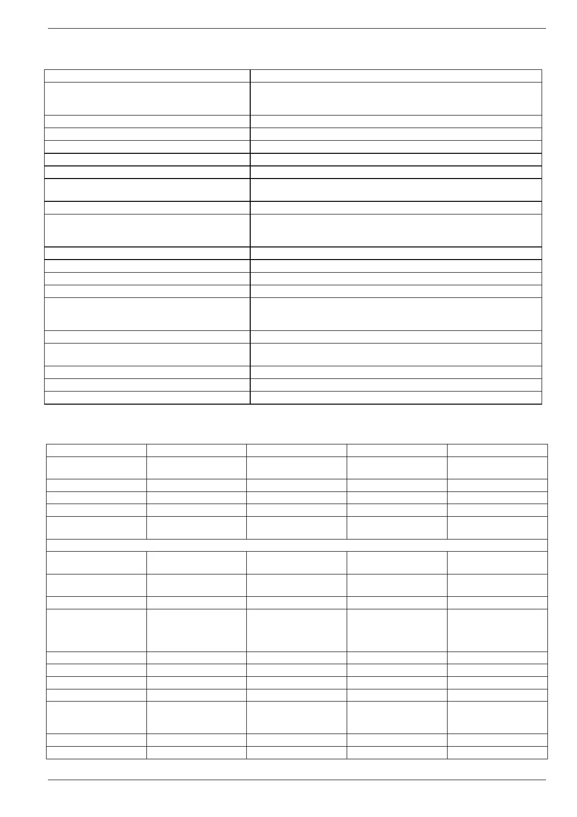
9.4.1. Parameters that can be set
Parameter Description
Optimisation on *)
The optimisation function sets its setpoint before the switching point in the
time program. In this way, the room temperature is reached at the switching
point. The optimisation time is limited to 3 hours
Minimum power-up time *) Minimum power-up time of the relay within the set cycles
Selection AM-PM/24 h Setting the clock (AM/PM 12 hours or 24 hours)
Accessories module type Radio clock
Reset time/temp program The time program (user program) can be reset to the factory settings
Heating/Cooling operation Switching between heating and cooling
Pump maintenance run *)
The pump forced operation activates the pump within 24 hours for approx.
20 s
Cycles *) The pulse width modulation can be changed to 3, 6 or 9 cycles per hour
Priority system time master
If more than one CM67RFMV accesses the heat generator via the relay
module HC60NG (R6660D), one CM67RFMV has to be set as the master
(system time generator)
Setting upper room temperature setpoint limit The maximum adjustable setpoint temperature at the CM67RFMV
Setting lower room temperature setpoint limit The minimum adjustable setpoint temperature at the CM67RFMV
Setting measured value offset The measured room temperature can be corrected by +/– 3 °C
Proportional range *) Band width
Communication failure *)
At a presetting of 0 the relay HC60NG/R6660D remains switched off. At a
setting of 1 the relay cycles in accordance with the set pulse width
modulation (display 9:Cr), relay 20 % On , 80 % Off
Reset installer mode parameter to factory setting Parameter settings can be reset to the factory settings
Maximum inlet setpoint
If the maximum inlet temperature limit is exceeded, the pump is switched
off directly
Minimum inlet setpoint Minimum inlet temperature limit
Mixing valve runtime Set the specified mixing valve runtime
Pump runtime If the mixing valve is closed, the pump continues to run for the set runtime
*) Parameter cannot be used for HM 80!
Parameter list CM67RFMV
Parameter Setting number Range Default setting Category
Optimisation 1:OP
0 (disabled)/
1 (enabled)
0 (disabled) 1
Min. on-time 2:Ot 1(1)5 1 min 1
AM-PM/24 h display 3:Cl 0 (24 h)/1(12 h) 0 (24 h) 1
Accessory module type 4:At {0,1} 1 0 (no module) 1
Reset time/temp
program
5:rP
0 (user setting)/
1 (factory setting)
0 (user setting) 1
Press the button PROG 2 in order to change to Category 2.
Heating/Cooling
operation on
6:HC 0 (cooling)/1 (heating) 1 (heating) 2
Enable maintenance run
pump
8:PE
0 (disabled) /
1 (enabled)
0 (disabled) 2
Number of cycles 9:Cr {3,6,9,12} 6 cycles/h 2
System time master 10:St
0 (Standard operation of
the room device) /
1 (Room device
configured as master)
0 (standard operation) 2
Upper temp. limit 11:UL 21 (1) 30 30 °C 2
Lower temp. limit 12:LL 5 (1) 16 5 °C 2
Temp. offset 13:tO -3.0 (0.1) 3.0 0 K 2
Proportional range 15:Pb 1.5 (0.1) 3.0 1.5 K 2
Communication failure 16:LC
0 (relay off)/
1 (relay 20 % on 80 %
off)
0 (relay off) 2
Maximum inlet setpoint 17:uF 0 °C to 99 °C 55 °C 2
Minimum inlet setpoint 18:LF 0 °C to 50 °C 15 °C 2
 Loading...