EasyManua.ls Logo

Honeywell NOTIFIER AM-8200 User Manual

Honeywell NOTIFIER AM-8200
77 pages
To Next Page IconTo Next Page
To Previous Page IconTo Previous Page
Page #58 background imageLoading...
Page #58 background image
PAGE - 54 Programming Manual AM_8200
NOTIFIER ITALIA Doc. M-162.1-AM8200-ENG Rev A2 AM8200_manu-prog-ENG
M
M
o
o
d
d
u
u
l
l
e
e
S
S
t
t
a
a
t
t
u
u
s
s
The display shows by default the first device of the first line. To select another device use the function keys
Esempio di visualizzazione dispositivi FAAST
SW Type programmed for output
of the device
Name =
Programmable Text max. 32 char
Status of the module
Displays the Fan speed
Displays the Air flow
Displays the Smoke level
Module Status depends on Module Type
(Input or Output)
Modify the Output Status of a Control Module
After selecting the “On/Off” field using the arrow
keys  , user can switch the control module
output pressing the OK
Key..
This action is indicated as:
Activated = ON
Deactivated = OFF
Modify the Output Status

Table of Contents

Other manuals for Honeywell NOTIFIER AM-8200

Question and Answer IconNeed help?

Do you have a question about the Honeywell NOTIFIER AM-8200 and is the answer not in the manual?

Honeywell NOTIFIER AM-8200 Specifications

General IconGeneral
BrandHoneywell
ModelNOTIFIER AM-8200
CategoryMeasuring Instruments
LanguageEnglish

Summary

General Description

Definitions

Hardware Address

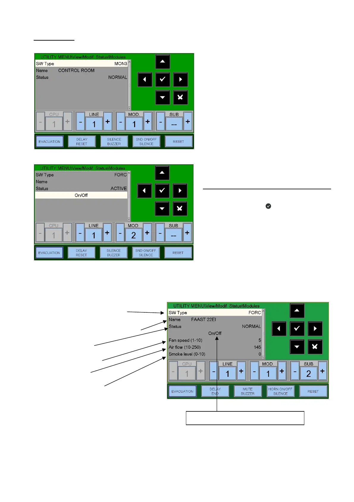
Device physical address on the loop, set via rotary switches or dip-switches.

SUB-ADDRESS

Programming for addressable modules, automatically assigned to components.

Front Panel Controls and Signallings

Keys with Dedicated Functions

Buttons for specific operations like EVACUATION, DELAY RESET, SILENCE.

Function Keys in LCD Touch Screen

Touchscreen keys for menu navigation and operations.

Front Panel LED Indications

Alarm (Red)

Indicates alarm status (flashing/lit).

Faults (Yellow)

Indicates fault status (flashing/lit).

User Interface Description

Functions and Access Level

Overview of functions and their required access levels/passwords.

Description of Keyboard Operation for Data Entry

Explains how to use the touch screen keyboard for data entry.

Programming Menu

Recommended Sequence for Panel Programming

Step-by-step guide for initial panel programming.

Programming - System Menu

Configures system-wide parameters.

Programming – System - System Type

Sets network type (Standalone, Net16, Net128).

Programming – System - System Address

Assigns the panel's device number on the CAN-BUS network.

Programming – System – Line

Configures line connection type (OPEN/CLOSED) and protocol (ADV/CLIP).

Programming – System - Timings

Sets delay times for alarms, sensor checks, and silencing.

Detectors Tab

Configures detector verification time.

Silence Tab

Configures self-silencing and silence inhibit times.

Faults Signalings Timings Tab

Configures mains fault detection time and fault signaling.

Programming - System - Password

Allows changing passwords for access levels.

Programming - Points

Detectors

Enters programming for addressable sensors.

Detectors Program Tab (Progr. of CBE Equations, Zone association)

Programs CBE and associates detectors with zones.

Detector Edit Tab (Common for All Sensors)

Allows removing or copying detector configurations.

Modules

Input Modules

Configuration for input modules.

Progr. Tab (Progr. of CBE Equation, Zone association)

Programs CBE and zone association for modules.

Option Tab (Progr. of Tracking and Led Blink)

Configures tracking and LED blink for modules.

Tab: Edit

Module edit functions (remove, copy, paste).

Output Modules:

Configuration for output modules.

FAAST

Details on FAAST units and their programming tabs.

Groups Programming Menu

Tab Progr. of CBE Associated with the Group

Programs CBE and association for groups.

High and Low Sensitivity Groups

Defines groups for high/low sensitivity based on time.

Zone Programming Menu

Programming - Configuration Menu

CPU and Loops

Configures CPU, installed boards, and line numbers.

Programming – Delete Programmings

Utility Menu

Special Parameters

Configures special parameters like drift warning.

Utility - History Log

Utility - View / Modify Status

Utility - Active Module List

Firmware Version

Firmware Update

Disable Menu

Modify

Modify Status - Detectors

Changes the enabled/disabled status of detectors.

Modify Status - Modules

Changes the enabled/disabled status of modules.

Modify Status - Zones

Changes the enabled/disabled status of zones.

System Disable

Procedure for system-wide disablement.

Test Menu

Zone Test

Starts a Walk-Test procedure for a selected zone.

Appendix A - Control-by-Event Equation

Control by Event Concept

Explains the concept of CBE for points, groups, and zones.

Rules for the Correct Syntax of the Equations

Rules for valid CBE equation syntax.

CBE Equation

Details on writing CBE equations using logical operators.

Operators Used in Control by Event Equation:

Explains operators like OR, AND, NOT.

Related product manuals